
Micro-machined multi-sensor providing 2-axes of acceleration sensing and 1-axis of angular rate sensing

Active Publication Date: 2005-01-25
ANALOG DEVICES INC
View PDF14 Cites 56 Cited by
  • Summary
  • Abstract
  • Description
  • Claims
  • Application Information

AI Technical Summary

Benefits of technology

By configuring the micro-machined multi-sensor to provide two pairs of electrically independent acceleration sense signals along two respective, mutually orthogonal acceleration axes in the plane of the silicon substrate, 2-axes of acceleration sensing and 1-axis of angular rate sensing can be obtained by suitably adding and / or subtracting the sense signals. Further, by configuring the micro-machined multi-sensor so that the first and second proof masses vibrate in antiphase along a common vibration axis, while being suspended from a common accelerometer frame, the multi-sensor device has two orthogonal mirror symmetries and can therefore be more easily centered on a die. In this way, the adverse effects of die surface area distortions can be reduced.

Problems solved by technology

The above-described conventional micro-machined multi-sensor is typically fabricated separately from its electronics by a process known as bulk micro-machining, which is a relatively expensive process for fabricating micro-machined devices.
However, the above-described conventional surface micro-machined gyroscope also has drawbacks.
As a result, there is typically at least a slight mismatch in the resonant frequencies of the respective proof masses, which can make it difficult to generate sufficient drive for vibrating the proof masses at velocities high enough to obtain detectable Coriolis accelerations.
Further, having separate accelerometer frames in the micro-machined multi-sensor device generally makes it harder to center the device on a die.
Distortions in the die surface area may therefore be asymmetrical relative to the micro-machined device, which can degrade the overall performance of the multi-sensor.
Another drawback is that this device generally provides only 1-axis of accelerometer tilt sensing and / or 1-axis of gyroscopic yaw sensing.

Method used


Image

  • Micro-machined multi-sensor providing 2-axes of acceleration sensing and 1-axis of angular rate sensing
  • Micro-machined multi-sensor providing 2-axes of acceleration sensing and 1-axis of angular rate sensing
  • Micro-machined multi-sensor providing 2-axes of acceleration sensing and 1-axis of angular rate sensing

Examples


embodiment 201

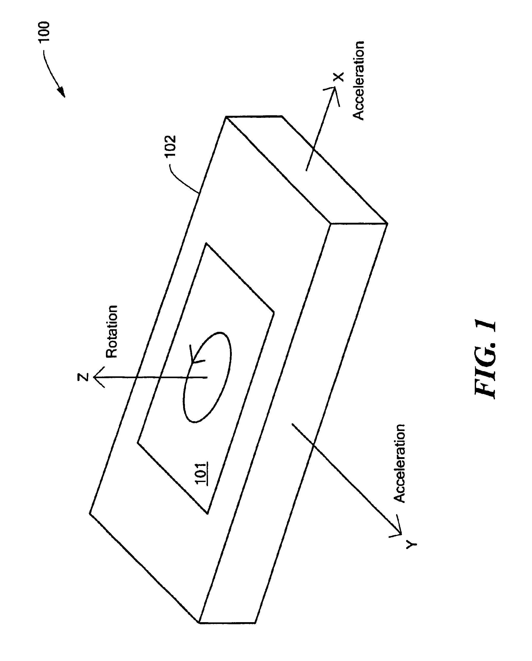
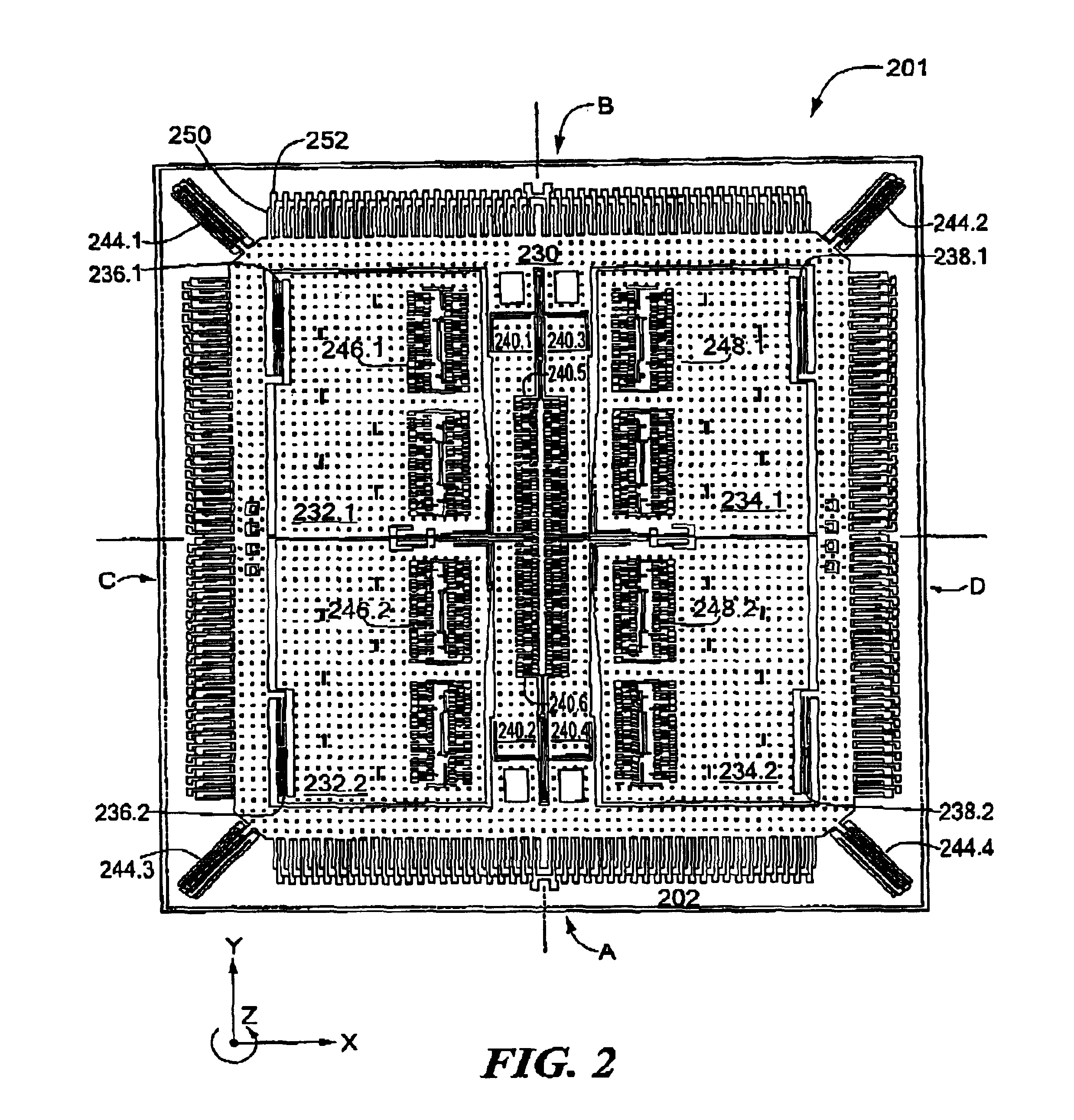
FIG. 2 depicts an illustrative embodiment 201 of the sensor 101 included in the micro-machined multi-sensor 100 (see FIG. 1). In the illustrated embodiment, the sensor 201 includes a rigid accelerometer frame 230, and proof masses 232.1-232.2 and 234.1-234.2, formed on a substrate 202. The proof masses 232.1-232.2 are suspended from the rigid frame 230 by resonator flexures 236.1-236.2, respectively, and the proof masses 234.1-234.2 are suspended from the rigid frame by resonator flexures 238.1-238.2, respectively. Moreover, the rigid frame 230 is anchored to the substrate by accelerometer flexures 244.1-244.4, which are diagonally disposed on the substrate 202.

The sensor 201 further includes drive electrode structures 246.1-246.2 and 248.1-248.2, and acceleration sense electrode structures A-D. As shown in FIG. 2, the drive electrode structures 246.1-246.2 and 248.1-248.2 include respective pluralities of drive electrodes (“fingers”), which are disposed in parallel and interdigitat...

embodiment 300

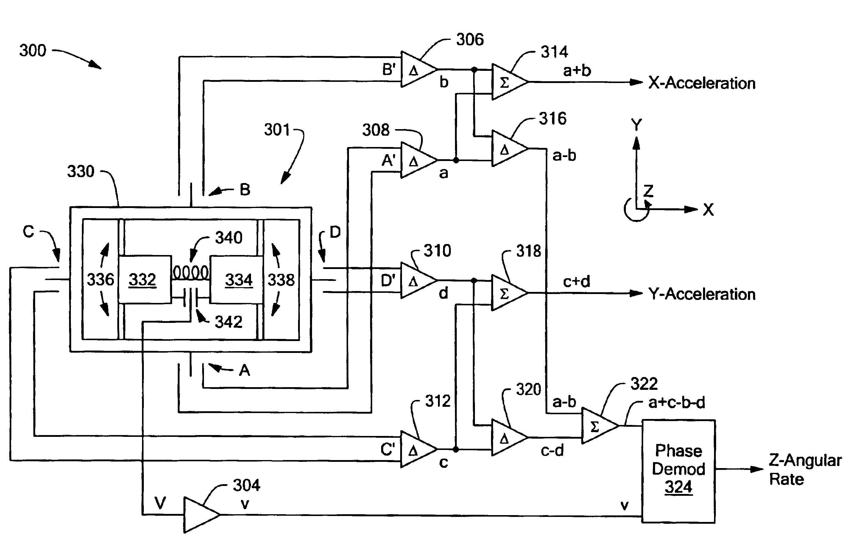
FIG. 3 depicts a schematic diagram of an illustrative embodiment 300 of the micro-machined multi-sensor 100 (see FIG. 1) according to the present invention. In the illustrated embodiment, the multi-sensor 300 includes a sensor 301, a transresistance amplifier 304, a plurality of difference amplifiers 306, 308, 310, 312, 316, and 320, a plurality of summing amplifiers 314, 318, and 322, and a phase demodulator 324. As described above, the proof masses 232.1-232.2 (see FIG. 2) are coupled together to move as a single mass, and the proof masses 234.1-234.2 (see FIG. 2) are similarly coupled together to move as a single mass. Accordingly, the sensor 301 includes a rigid accelerometer frame 330 representing the rigid frame 230 (see FIG. 2), a first proof mass 332 representing the proof masses 232.1-232.2, and a second proof mass 334 representing the proof masses 234.1-234.2.

Specifically, the first proof mass 332 is suspended from the rigid frame 330 by resonator flexures 336, which are r...


PUM


Abstract

A micro-machined multi-sensor that provides 2-axes of acceleration sensing and 1-axis of angular rate sensing. The multi-sensor includes a rigid accelerometer frame, a first proof mass, and a second proof mass. The substrate has two associated acceleration axes in the plane of the substrate, and one associated rotation axis perpendicular to the acceleration axes. The proof masses have a common vibration axis, which is perpendicular to the rotation axis. The multi-sensor further includes a drive electrode structure for causing the proof masses to vibrate in antiphase, a first pair of acceleration sense electrode structures disposed along one of the acceleration axes, and a second pair of acceleration sense electrode structures disposed along the other acceleration axis. The multi-sensor adds the sense signals provided by the respective sense electrode pairs to extract information pertaining to acceleration sensing along the acceleration axes, and adds the differences of the sense signals provided by the respective sense electrode pairs to extract information pertaining to angular rate sensing relative to the rotation axis.

Description

STATEMENT REGARDING FEDERALLY SPONSORED RESEARCH OR DEVELOPMENTN / ABACKGROUND OF THE INVENTIONThe present invention relates generally to integrated acceleration and angular rate sensors (“multi-sensors”), and more specifically to a silicon micro-machined multi-sensor capable of providing 2-axes of acceleration sensing and 1-axis of angular rate sensing.Silicon micro-machined multi-sensors are known that comprise at least one accelerometer for providing an indication of acceleration sensing and / or angular rate sensing in a single sensor device. A conventional silicon micro-machined multi-sensor, such as the silicon micro-machined multi-sensor described in U.S. Pat. No. 5,392,650 issued Feb. 28, 1995 entitled MICRO-MACHINED ACCELEROMETER GYROSCOPE, comprises a pair of accelerometers, in which each accelerometer includes a respective accelerometer frame and a respective proof mass suspended from the frame by a plurality of flexures. The conventional micro-machined multi-sensor has a sin...

Claims


Application Information

Patent Timeline
IPC IPC(8): G01C19/56G01P15/125G01P15/00G01C19/5719G01P15/18
CPCG01C19/5719G01P15/18G01P15/125G01P2015/082
Inventor GEEN, JOHN A.
Owner ANALOG DEVICES INC
Learn More