Steam cycle efficiency improvement with pre-economizer
a pre-economizer and steam cycle technology, applied in the direction of preheating, light and heating equipment, papermaking, etc., can solve the problems of increasing the exit gas temperature of the boiler, reducing the power generation, and reducing the steam load, so as to increase the available low-pressure steam. , the effect of cost-effectiv
- Summary
- Abstract
- Description
- Claims
- Application Information
AI Technical Summary
Benefits of technology
Problems solved by technology
Method used
Image
Examples
first embodiment
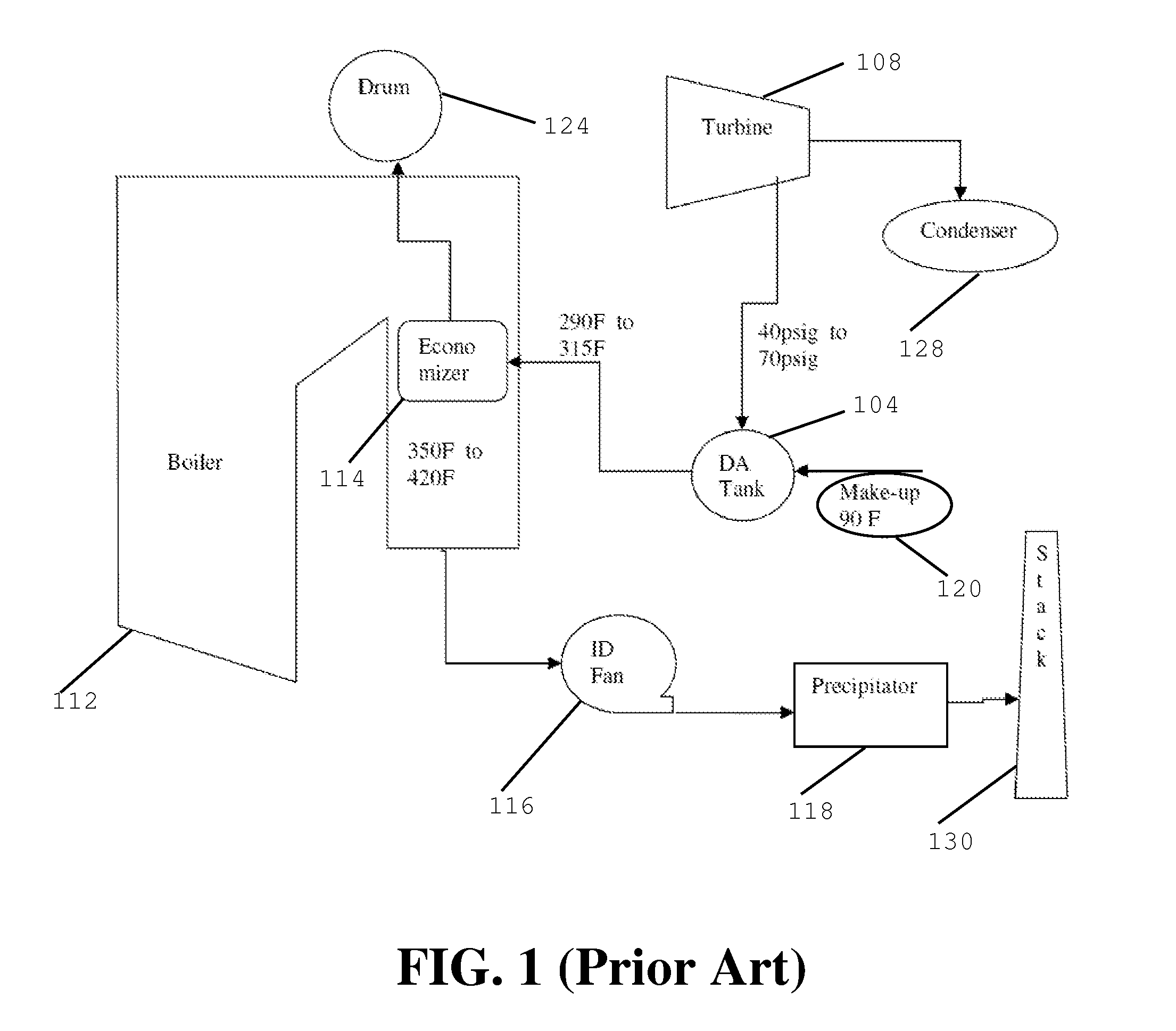
[0021]Referring to the drawings generally, wherein like reference numerals designate the same or functionally similar elements throughout the several drawings, and to FIG. 3 in particular, there is shown a schematic illustration of the present invention, comprising a pre-economizer employed as part of a steam cycle steam turbine installation, generally referred to as 300. In this and the following figures, and solely for the sake of convenience to the reader, the “300” series of reference numerals refer to elements in FIG. 3, while the “400” series of reference numerals refer to elements in FIG. 4, etc. Similarly, the last two numbers in the various reference numerals designate the same or functionally similar elements throughout the several drawings; e.g., 310, 410, 510 etc. refers to the pre-economizer in FIGS. 3, 4 and 5 etc. Also, temperatures (degrees F.), pressures (pounds per square inch gage or absolute—psig, psia) and flow rates (thousands of pounds per hour—kpph) are provi...
second embodiment
[0028]With reference to FIG. 4, which is a schematic illustration of the present invention, generally referred to as 400, a heat exchanger 422 is installed after the DA tank 404 that removes heat from the feedwater and adds it to the incoming make-up water 420. This arrangement allows the pressure on the DA tank 404 to remain at the mill's low-pressure steam extraction.
third embodiment
[0029]With reference to FIG. 5, which is a schematic illustration of the present invention, generally referred to as 500, make up water is delivered directly to the DA tank 504, which will effectively remove air and other corrosive gases at pressures much closer to atmospheric. A pressure reducing valve 536 is associated with the DA tank 504 for reducing the pressure therein to a level close to atmospheric. The feedwater 520 is then conveyed to the pre-economizer 510 with the assistance of a pump 534. After the water is heated in the pre-economizer 510 it is then delivered away from the boiler 512, back to the DA tank 504 and heated with a feedwater heater (or heaters) 532. The water is then delivered to the economizer 514.
[0030]With reference to FIG. 6, which is a schematic illustration of a third embodiment of the present invention, generally referred to as 600, make-up water is delivered to the heat exchanger 622 and, from there, to the DA tank 604. This is in contrast to the emb...
PUM
 Abstract
Description
Claims
Application Information
 - R&D
- Intellectual Property
- Life Sciences
- Materials
- Tech Scout
- Unparalleled Data Quality
- Higher Quality Content
- 60% Fewer Hallucinations
Browse by: Latest US Patents, China's latest patents, Technical Efficacy Thesaurus, Application Domain, Technology Topic, Popular Technical Reports.
© 2025 PatSnap. All rights reserved.Legal|Privacy policy|Modern Slavery Act Transparency Statement|Sitemap|About US| Contact US: help@patsnap.com


