
Multiphase flow meter for subsea applications using hydrate inhibitor measurement

a multi-phase flow meter and hydrate inhibitor technology, which is applied in the field of hydrocarbon production flow analysis in the presence of hydrate inhibitors, can solve the problems of affecting the flow rate of hydrocarbons,

Active Publication Date: 2012-02-23
WEATHERFORD TECH HLDG LLC
View PDF2 Cites 39 Cited by
  • Summary
  • Abstract
  • Description
  • Claims
  • Application Information

AI Technical Summary

Benefits of technology

The present invention provides methods, systems, and computer-readable media for using a hydrate inhibitor injection rate to determine the flow rates of a fluid mixture's components. This allows for better control and monitoring of the flow rates of liquids and gases in the mixture, which can improve the efficiency and safety of oil and gas drilling operations.

Problems solved by technology

However, known measurement techniques suffer from their own unique drawbacks and / or limitations, such as frequent calibrations, as well as sensitivity to salinity, gas, and emulsions.
In addition, current subsea multiphase meters can be prohibitively expensive.
Water in gas wells introduces the prospect of hydrate formation that may impede or plug the flow and create unsafe flowing conditions.
Furthermore, gas wells that have a high flow rate may produce large pressure drops across chokes and other flow-area changes.
At these locations, Joule-Thomson cooling can reduce temperatures significantly, which may result in severe hydrate problems in a matter of hours or even minutes if water is present.
Serious problems result once the hydrates form and block or limit flow.
However, cleaning and treatment procedures required at the surface to remove the hydrate inhibitor along with high costs of the inhibitor itself may contribute to production expenses.
Therefore, injection of methanol, as an exemplary hydrate inhibitor, increases costs when done at levels beyond that required based on the water that is present.
Known measurement techniques are not well-suited to make low water measurements especially when the fluid flow is further complicated by the hydrate inhibitor injection.

Method used


Image

  • Multiphase flow meter for subsea applications using hydrate inhibitor measurement
  • Multiphase flow meter for subsea applications using hydrate inhibitor measurement
  • Multiphase flow meter for subsea applications using hydrate inhibitor measurement

Examples


Embodiment Construction

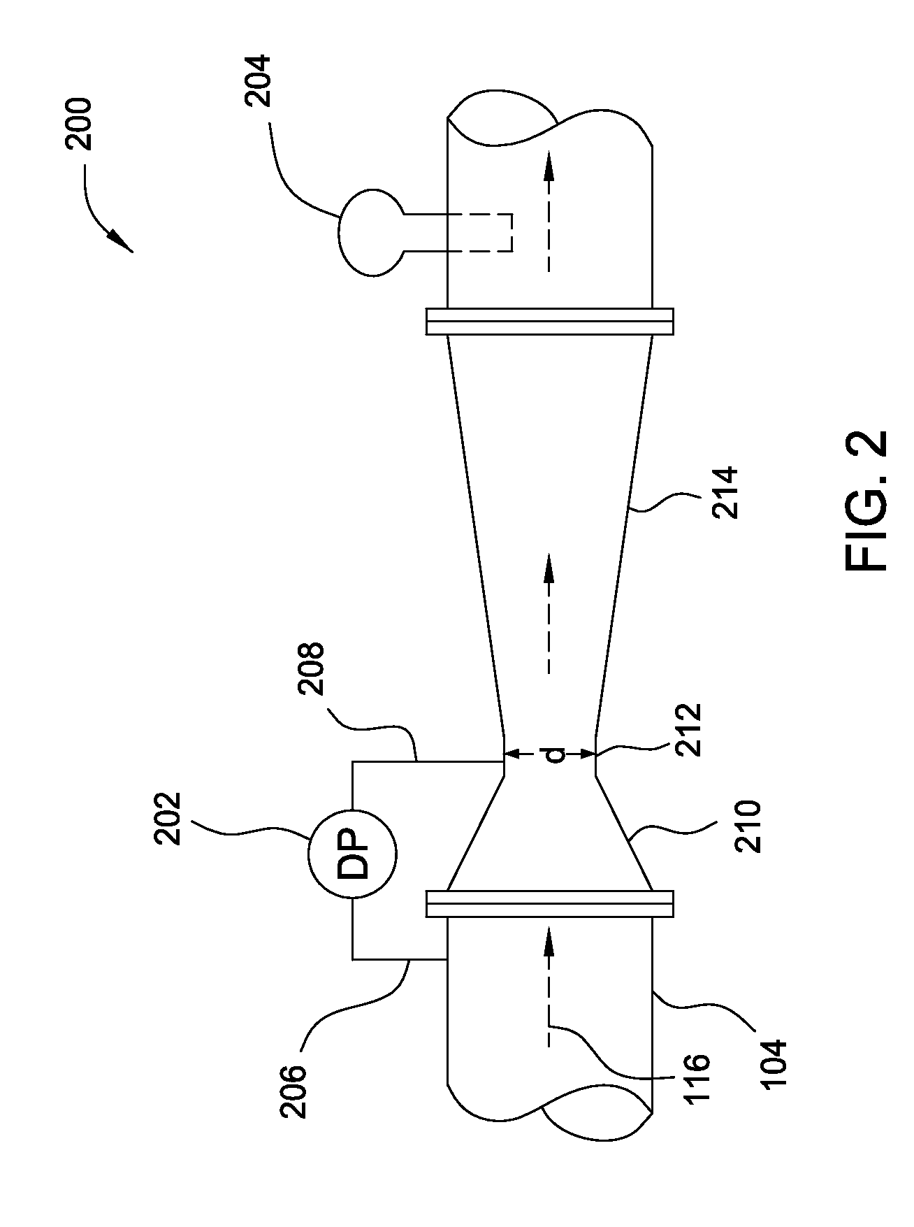
[0021]Embodiments of the invention generally relate to subsea multiphase flow meters capable of determining phase fractions (relative concentrations) within a multiphase fluid mixture, in the presence of an injected hydrate inhibitor. Combining this phase fraction information with a hydrate inhibitor injection rate (HIIR) enables resolving oil and water flow rates for the phase fractions. The liquid flow rates and a total combined flow rate of the fluid mixture—determined based on a differential pressure of the fluid mixture through a given area—enable resolving a gas flow rate.

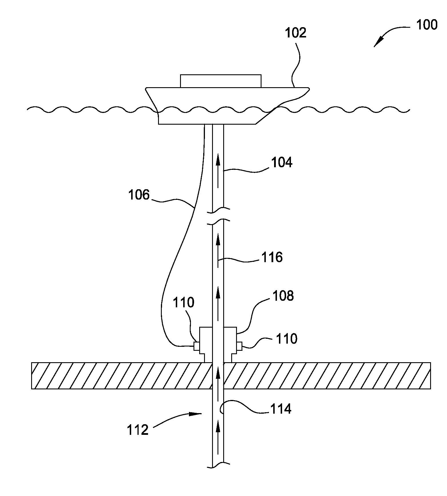
[0022]The production of oil and / or gas with a subsea production system 100 such as that depicted in FIG. 1 is a common practice in the oil and gas industry. A riser 104 may extend from a vessel 102 at the surface of the sea to a subsea well 112 at the sea floor. It will be readily apparent to those skilled in the art that the diameter of the riser 104 may be varied as desired, to typically coincide with the i...


PUM


Abstract

Methods and apparatus for determining phase fractions (relative concentrations) within a multiphase fluid mixture, in the presence of an injected hydrate inhibitor. Combining this phase fraction information with a hydrate inhibitor injection rate (HIIR) enables resolving oil and water flow rates for the phase fractions. The liquid flow rates and a total combined flow rate of the fluid mixture—determined based on a differential pressure of the fluid mixture through a given area—enable resolving a gas flow rate.

Description

BACKGROUND OF THE INVENTION[0001]1. Field of the Invention[0002]Embodiments of the invention generally relate to flow analysis for hydrocarbon production and, more particularly, to flow rate analysis in a multiphase fluid in the presence of a hydrate inhibitor.[0003]2. Description of the Related Art[0004]Oil and / or gas operators periodically measure water / oil / gas phase fractions (relative concentrations) of an overall production fluid flow in order to aid in optimizing well production, allocating royalties, inhibiting corrosion / hydrates (e.g., based on the amount of water), and generally determining the well's performance. Multiphase metering is desired for measuring individual well production of oil, water, and gas. In subsea applications, since many production systems involve commingling of multiple wells prior to the riser, subsea multiphase metering may be the only option to get individual well rates other than a measure-by-difference technique.[0005]Various approaches for analy...

Claims


Application Information

Patent Timeline
Patent Type & Authority Applications(United States)
IPC IPC(8): E21B47/10G01F1/74
CPCG01F1/44G01F1/74G01N21/3577G01N21/35G01N21/359G01F1/88
Inventor LIEVOIS, JOHNRAMAKRISHNAN, VIJAYADEJUYIGBE, BABAJIDE
Owner WEATHERFORD TECH HLDG LLC
Learn More