
Susceptor support system

Inactive Publication Date: 2012-02-23
STMICROELECTRONICS SRL
View PDF5 Cites 7 Cited by
  • Summary
  • Abstract
  • Description
  • Claims
  • Application Information

AI Technical Summary

Benefits of technology

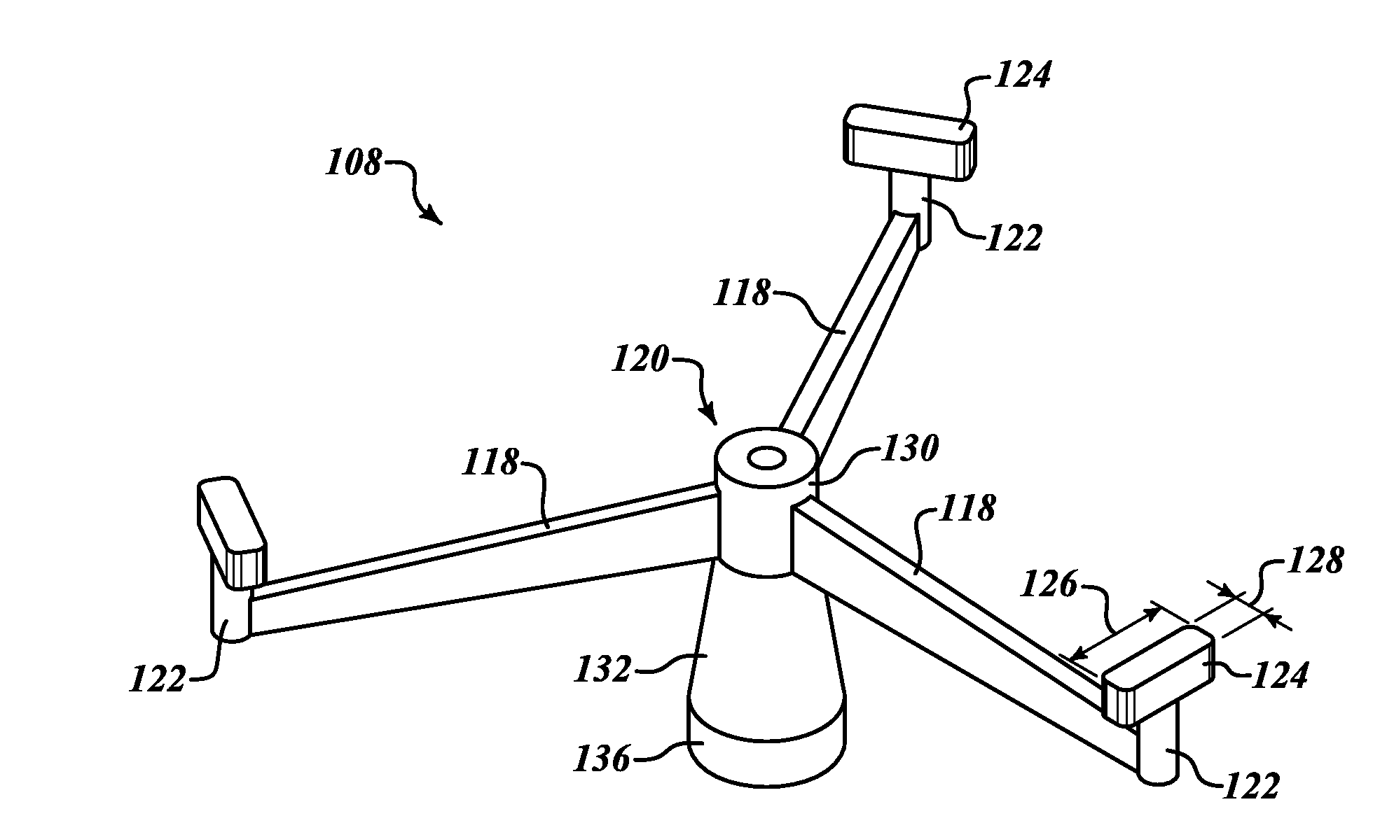
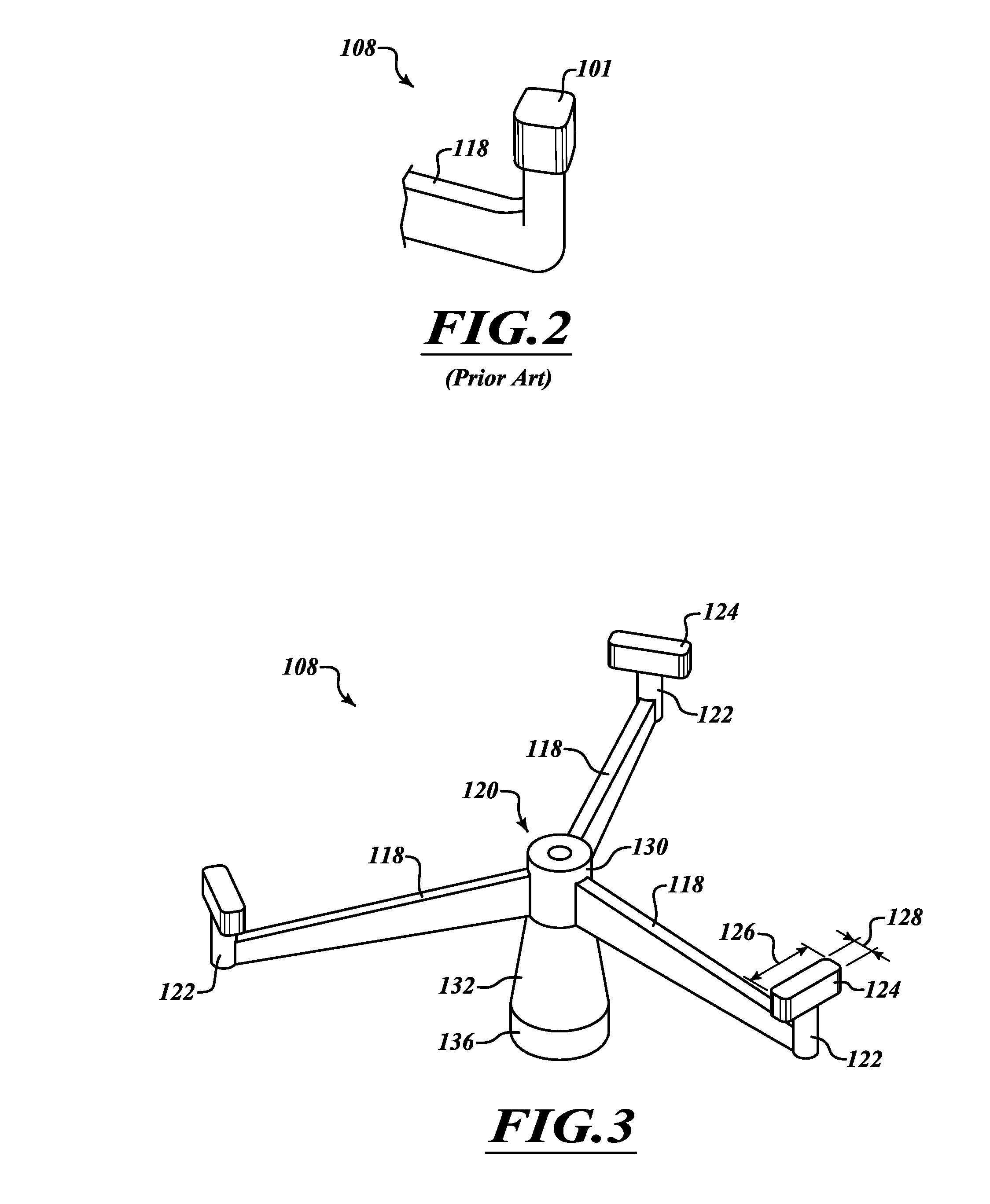
[0019]In one embodiment of the present disclosure, a susceptor support device is provided for use in a deposition chamber to provide stability and to rotate a susceptor to ensure even heating of a wafer placed upon the susceptor. The susceptor support device includes a susceptor support and a rotatable shaft. The shaft is an elongated quartz cylinder having a first end configured to be received by a motor and a second end configured to receive the susceptor support.
[0023]Previous susceptor support and shaft designs may undergo up to 5,000 processes or depositions before degradation is noted. As described above, this degradation may occur at the contact area between the tip of the susceptor support and the susceptor itself, or at the contact area between the susceptor support and the rotatable shaft. One embodiment of the present disclosure is the susceptor support and system design that extends the life of the susceptor support system beyond 5,000 processes while still ensuring stability in holding up the susceptor and eliminating wobbling while turning. For example, the susceptor support having tips with a length longer than a width can extend the operational life of the susceptor support to be more than 10,000 wafer runs.
[0025]The elongated tips and locking mechanism between the hub and rotatable shaft enable longer period of usage between replacements, and thus provide cost savings.

Problems solved by technology

However, with extended exposure to hydrocholoric (HCL) gas and extreme temperature, small features of the susceptor support and the shaft degrade, which can impact support stability.
Also, the surfaces of the hub and the shaft that interact can become smooth so that it is difficult to turn the susceptor support with the shaft.
Reduced friction between the hub and shaft influences the rotation generated by the motor and negatively impacts the deposition process.
But after a certain number of uses and repeated exposure to chemical gases, the quartz susceptor support experiences degradation and generally has to be periodically replaced with a new one.

Method used


Image

  • Susceptor support system
  • Susceptor support system
  • Susceptor support system

Examples


Embodiment Construction

[0045]In the following description, certain specific details are set forth in order to provide a thorough understanding of various embodiments of the disclosure. However, one skilled in the art will understand that the disclosure may be practiced without these specific details. In some instances, well-known structures associated with the chemical vapor deposition chambers have not been described in detail to avoid obscuring the descriptions of the embodiments of the present disclosure.

[0046]Unless the context requires otherwise, throughout the specification and claims that follow, the word “comprise” and variations thereof, such as “comprises” and “comprising,” are to be construed in an open, inclusive sense, that is, as “including, but not limited to.”

[0047]Reference throughout this specification to “one embodiment” or “an embodiment” means that a particular feature, structure, or characteristic described in connection with the embodiment is included in at least one embodiment. Thu...


PUM

PropertyMeasurementUnit
Lengthaaaaaaaaaa
Widthaaaaaaaaaa

Abstract

The present disclosure is directed to a susceptor support that includes a hub and a plurality of arms extending radially from the hub, where each arm has a terminal end positioned away from the hub. The susceptor support also includes a plurality of elongated rectangular tips formed at the terminal end of each arm, each tip having a length and a width, wherein the length is greater than the width.

Description

BACKGROUND[0001]1. Technical Field[0002]The present disclosure relates generally to a susceptor support system used in a semiconductor processing chamber.[0003]2. Description of the Related Art[0004]One of the more common silicon manufacturing processes is a chemical process known as CVD, or chemical vapor deposition. By the chemical vapor deposition process, thin layers of chemical material such as silicon and silicon compounds are deposited upon a wafer by exposing the wafer to the vaporized chemical at high temperature in a reactor chamber. This process generally produces high purity and high performance solid materials.[0005]A chemical vapor deposition generally takes place in a reaction chamber. There are many reaction chamber designs and configurations, each with a different method for performing the fundamental operations, which are: dispensing gases, controlling temperature, and removing byproducts. Gases dispensed into the chamber react not only with materials on a surface ...

Claims


Application Information

Patent Timeline
IPC IPC(8): B05C13/00
CPCC23C16/4584B05C13/02
Inventor GATCHALIAN, ROY G.SORIANO, JOSEPH GREGORIOCHER, HENG HEE
Owner STMICROELECTRONICS SRL
Learn More