Water Fraction Measuring Sensor and Method
a technology of water fraction and sensor, which is applied in seismology, well accessories, and water production from hydrocarbon fluids, etc., can solve the problems of inconvenient or cost-effective water fraction measurement, inability to conventionally or cost-effectively record water fraction, and high cost of water fraction measurement by running a wireline sonde. , to achieve the effect of accurate estimation of water and oil fraction, simple operation, and reliable over tim
- Summary
- Abstract
- Description
- Claims
- Application Information
AI Technical Summary
Benefits of technology
Problems solved by technology
Method used
Image
Examples
first embodiment
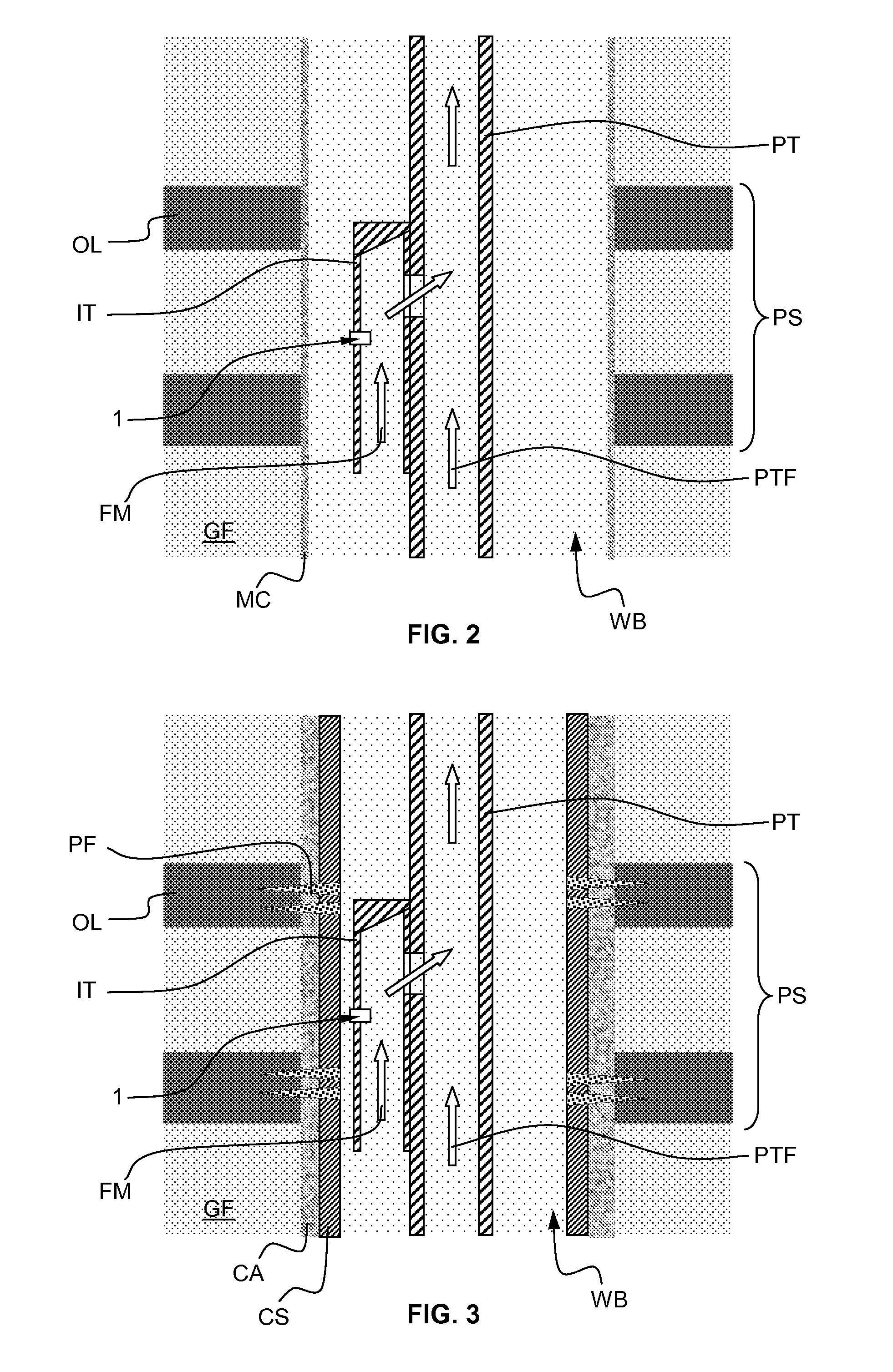
[0038]FIG. 2 is a front cross-section view of a geological formation GF schematically depicting a sensor 1 in an uncased vertical borehole WB. The well bore WB is an uncased borehole that may be covered by a mudcake MC. A production tubing PT directs the produced fluid mixture flow PTF towards the surface. An instrumented tubing IT is coupled outside the production tubing PT. For example, both tubing are welded together. The instrumented tubing IT may have a length ranging from a few dozen of centimeters to a meter, and a diameter of the order of a typical production tubing diameter. A first end of the instrumented tubing is opened, while the second end is closed. The instrumented tubing further comprises a lateral hole. For example, both tubings are coupled in a parallel manner and comprise a hole to communicate with each other. Thus, the fluid mixture flowing out of the producing zone PS may flow into the production tubing PT after having flown through the instrumented tubing IT....
second embodiment
[0067]FIG. 6 is a front cross-section view in a geological formation GF schematically depicting the sensor 1 of the present invention in an uncased borehole.
[0068]The producing hydrocarbon well WB comprises an uncased borehole in a geological formation GF comprising at least a layer of oil OL. The wall of the borehole may comprise a mudcake MC. It further comprises a completion consisting of a production tubing PT. It may further comprise a packer and a series of perforations in a cased portion of the borehole (not shown). A produced hydrocarbon fluid mixture PTF flows towards the surface through the production tubing PT. In the production zone PS, the instrumented tubing IT comprising the sensor 1 is coupled to the production tubing PT. The hydrocarbon fluid mixture flowing from the production zone PS flows into the production tubing through the instrumented tubing IT.
[0069]The instrumented tubing IT may further comprise a mixing device MD in order to properly mix the fluid mixtur...
third embodiment
[0072]FIG. 7 is a front cross-section view of a geological formation GF schematically depicting a sensor 1 in an uncased borehole. In this embodiment, the instrumented tubing IT further comprises a control valve CV to choke the hydrocarbon fluid mixture production of the producing zone PS. The sensor 1 is coupled to the control valve CV in order to form a production controlling system of the associated producing zone PS. In a preferable aspect of the present embodiment, the sensor controls the operation of the valve as a function of the measured water holdup / fraction in the fluid mixture FM produced by the producing zone PS. In particular, the control valve CV may be closed and the production of the specific producing zone PS may be interrupted when the water holdup / fraction exceeds a determined water fraction threshold value. However, the control valve CV may be controlled in any number of manners, such as by an operator at surface or independently based on a timer.
[0073]The other...
PUM
 Abstract
Description
Claims
Application Information
 - R&D
- Intellectual Property
- Life Sciences
- Materials
- Tech Scout
- Unparalleled Data Quality
- Higher Quality Content
- 60% Fewer Hallucinations
Browse by: Latest US Patents, China's latest patents, Technical Efficacy Thesaurus, Application Domain, Technology Topic, Popular Technical Reports.
© 2025 PatSnap. All rights reserved.Legal|Privacy policy|Modern Slavery Act Transparency Statement|Sitemap|About US| Contact US: help@patsnap.com


