Eureka AIR delivers breakthrough ideas for toughest innovation challenges, trusted by R&D personnel around the world.

Method for performing diagnostics or software maintenance for a vehicle

Active Publication Date: 2012-02-16
DEERE & CO
View PDF2 Cites 86 Cited by
  • Summary
  • Abstract
  • Description
  • Claims
  • Application Information

AI Technical Summary

Benefits of technology

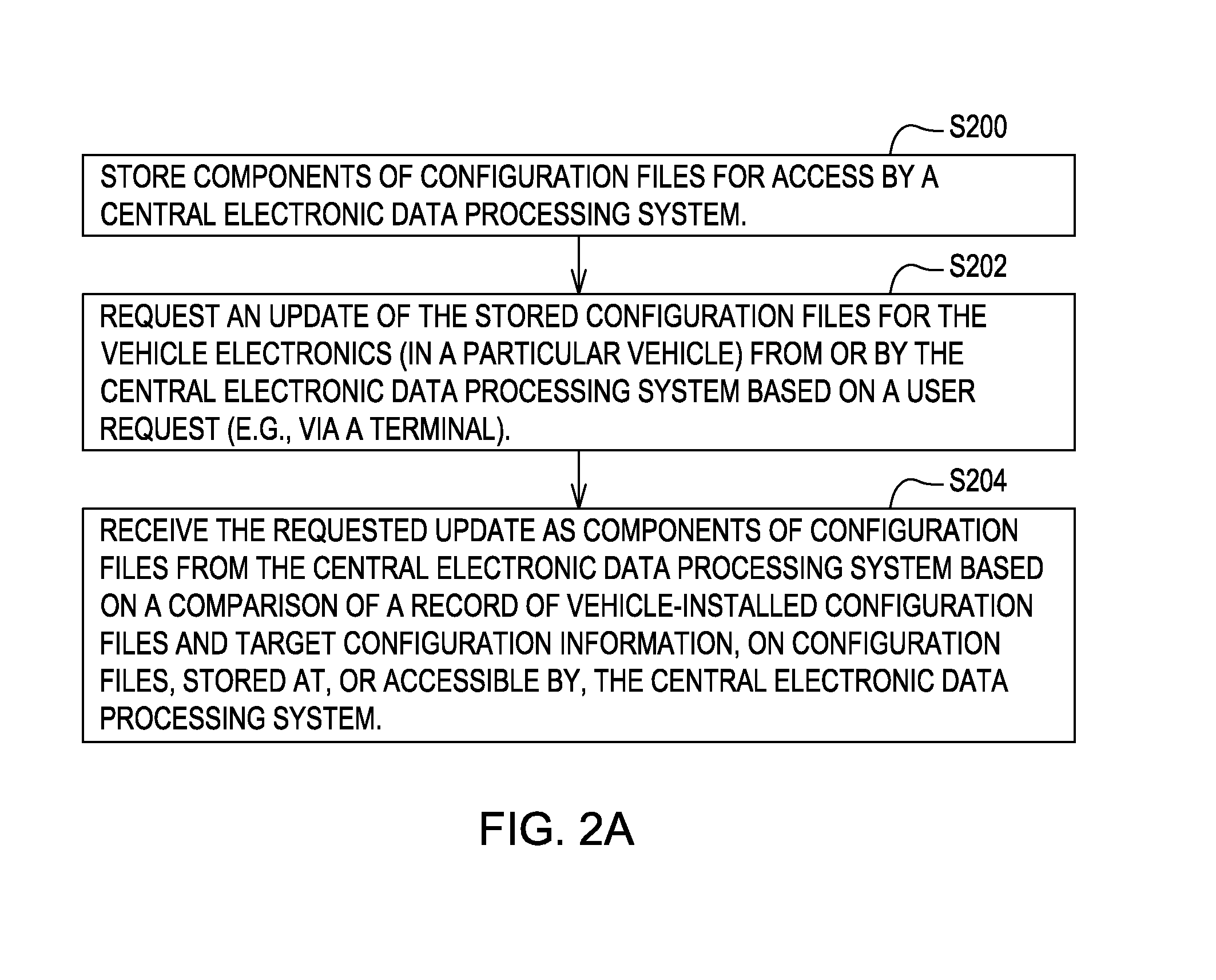
[0007]In accordance with one embodiment, a method for performing diagnostics or software maintenance on a vehicle comprises storing components of configuration files in, or accessible by, a central data processing system. An update of the configuration files is requested for the vehicle from a central electronic data processing system based on a user request. The requested update of components of configuration files are received from the central electronic data processing system based on a comparison of a record of the vehicle-installed configuration files and target configuration information on configuration files stored at the central electronic data processing system.

Problems solved by technology

Such transmission tends to inefficiently use one or more communications channels between central processing center and vehicle electronic.
A land-based communication channel might be unavailable or unreliable where the vehicle and associated vehicle electronics are located in rural areas such that a satellite communications channel is required.
For example, the transmission of entire configuration files, and hence remote diagnostics, may not be economically feasible, where more expensive satellite communications channels are required to handle a significant throughput of data in entire configuration files.
In certain prior art, the diagnostic capabilities may be limited to the transmission rate capacity of a vehicle data bus, such as a controller area network (CAN) data bus.
Accordingly, engine control events that occur at higher rates than the transmission rate capacity of the vehicle data bus may be ignored in certain prior art diagnostic systems, which can lead to less accurate or more time-consuming diagnostic procedures.

Method used


Image

  • Method for performing diagnostics or software maintenance for a vehicle
  • Method for performing diagnostics or software maintenance for a vehicle
  • Method for performing diagnostics or software maintenance for a vehicle

Examples


Embodiment Construction

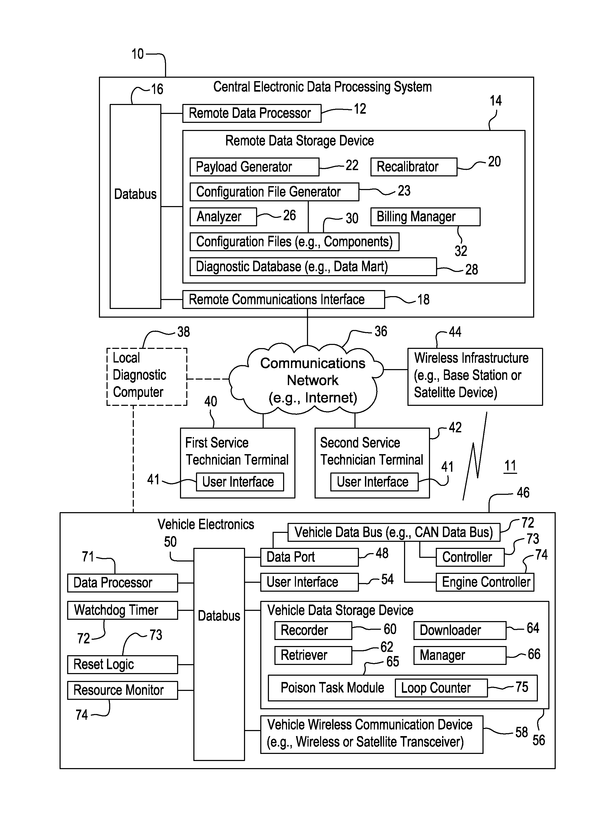
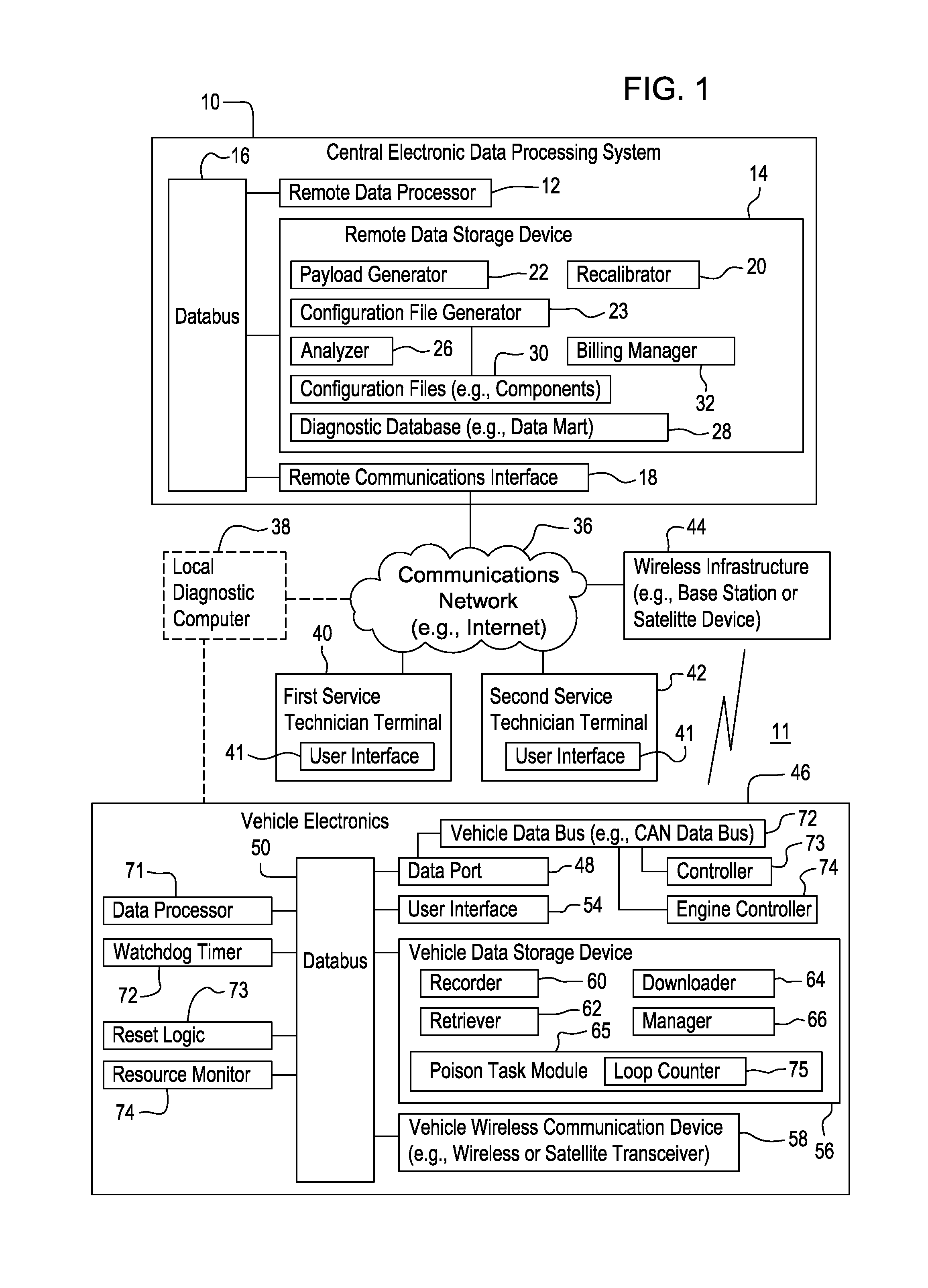
[0021]In accordance with one embodiment, FIG. 1 illustrates a remote diagnostic system 11. In one embodiment, the remote diagnostic system 11 comprises a central electronic data processing system 10 that is capable of communicating with vehicle electronics 46 via a communications network 36 and wireless infrastructure 44.

[0022]The central electronic data processing system 10 and wireless infrastructure 44 are coupled to an electronic communications network 36 (e.g., the Internet). One or more service technician terminals (e.g., first service technician terminal 40 and a second service technician terminal 42) are capable of communicating with the central electronic data processing system 10 via the communications network 36. One or more service technician terminals (40, 42) are capable of communicating with the vehicle electronics 46 via the communications network 36 and the wireless infrastructure 44.

[0023]In an alternative embodiment, a service technician or user may use a local di...


PUM


Abstract

A method for performing diagnostics or software maintenance on a vehicle comprises storing components of configuration files in a central processing system. An update of the configuration files is requested for the vehicle from a central electronic data processing system based on a user request. The requested update of components of configuration files are received from the central electronic data processing system based on a comparison of a record of the vehicle-installed configuration files and target configuration information on configuration files stored at the central electronic data processing system.

Description

[0001]This document (including the drawings) claims priority and the benefit of the filing date based on U.S. provisional application No. 61 / 373,493, filed Aug. 13, 2010 under 35 U.S.C. §119 (e), where the provisional application is hereby incorporated by reference herein.FIELD OF THE INVENTION[0002]This invention relates to a method for performing diagnostics or software maintenance for a vehicle.BACKGROUND OF THE INVENTION[0003]In certain prior art, remote diagnostics and analysis of the performance of vehicle may require the storage and transmission of entire configuration files from a central processing center to vehicle electronics. Such transmission tends to inefficiently use one or more communications channels between central processing center and vehicle electronic. A land-based communication channel might be unavailable or unreliable where the vehicle and associated vehicle electronics are located in rural areas such that a satellite communications channel is required. For ...

Claims


Application Information

Patent Timeline
IPC IPC(8): G06F19/00
CPCG07C5/008G06F11/3013G06F11/0739G07C5/085G06F11/0757G06F11/0793G06F11/3003G06F11/3409G06F11/3466G06F2201/81G06F2201/865G06F2201/88G06F11/2294
Inventor JOHNSON, MICHAEL R.COLAVITA, DANIELPULLEN, TAMMY R.
Owner DEERE & CO
Why Eureka
Eureka Blog
Learn More