
Apparatus and method for controlled application of liquid streams to a substrate

Inactive Publication Date: 2012-02-09
LOVE III FRLIN S +4
View PDF2 Cites 5 Cited by
  • Summary
  • Abstract
  • Description
  • Claims
  • Application Information

AI Technical Summary

Benefits of technology

[0004]The present invention provides advantages and alternatives over prior constructions and practices by providing an improved system for application of liquid streams to a substrate. The system of the present invention incorporates open face flow channels prior to discharge along an unconstrained flow path. The present invention further provides an improved self-aligning modular assembly for delivery of impingement stream to the liquid streams. The present invention further provides an improved arrangement for collection of the liquid stream in a diverted flow path in response to application of the impingement stream, without excess residue build-up.

Problems solved by technology

While the prior systems work very well, it is a continuing challenge to provide improved definition in the applied pattern across the substrate while nonetheless delivering a sufficient quantity of dye or other liquid to the substrate to provide complete treatment.
It is also a continuing challenge to provide reduced complexity in the system set-up as well as enhanced functionality in the collection of unused liquid.

Method used


Image

  • Apparatus and method for controlled application of liquid streams to a substrate
  • Apparatus and method for controlled application of liquid streams to a substrate
  • Apparatus and method for controlled application of liquid streams to a substrate

Examples


Embodiment Construction

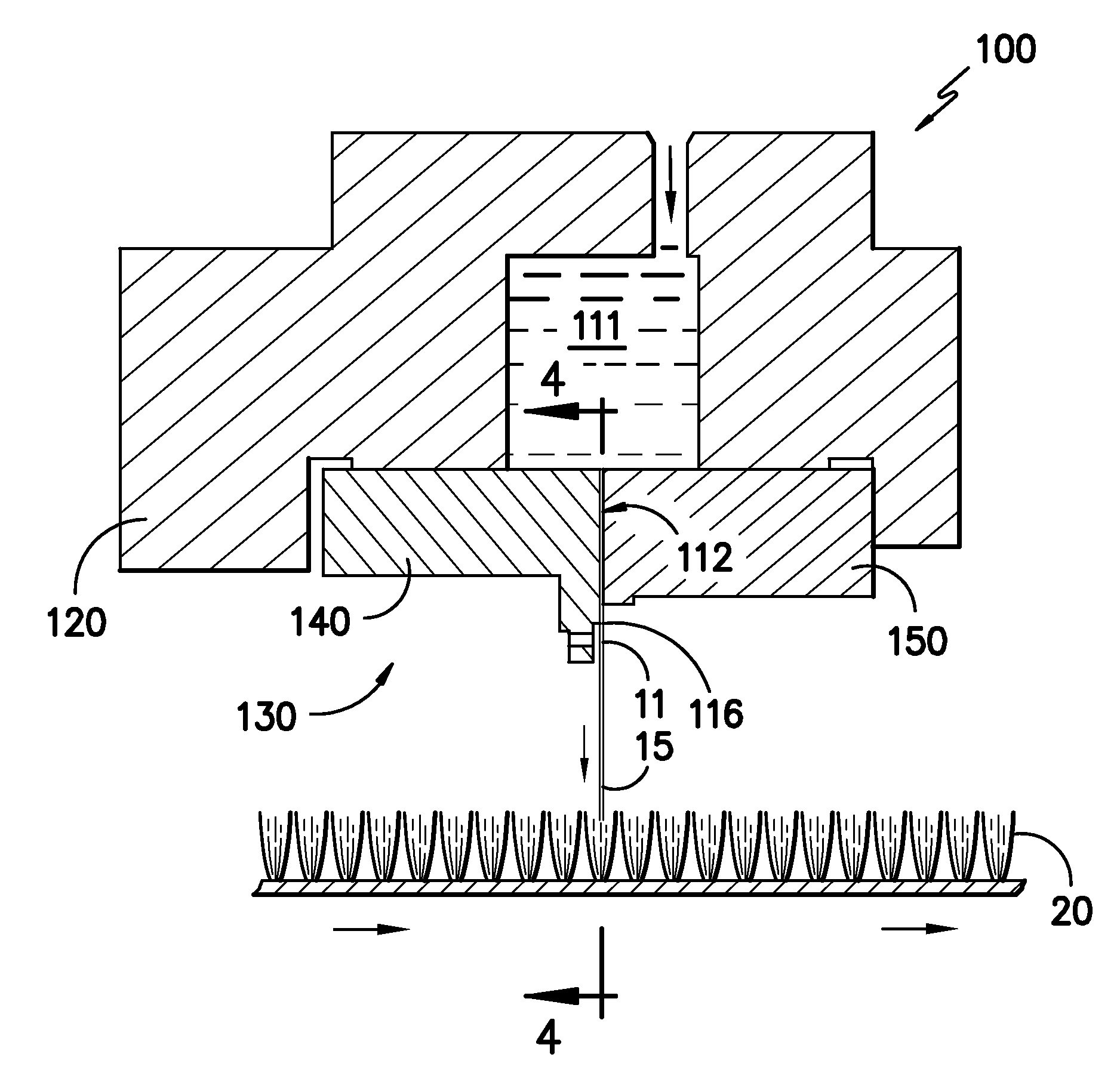
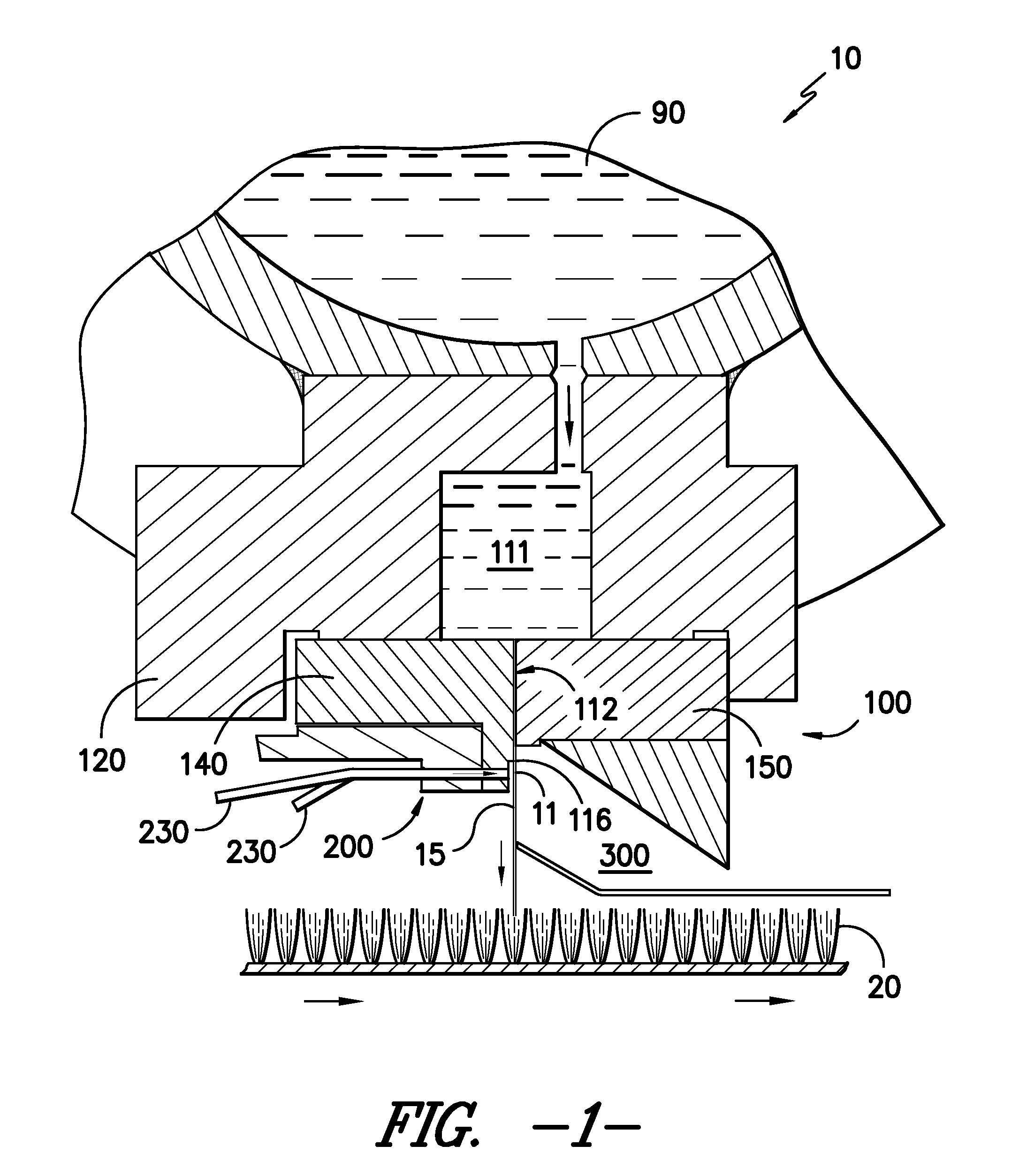
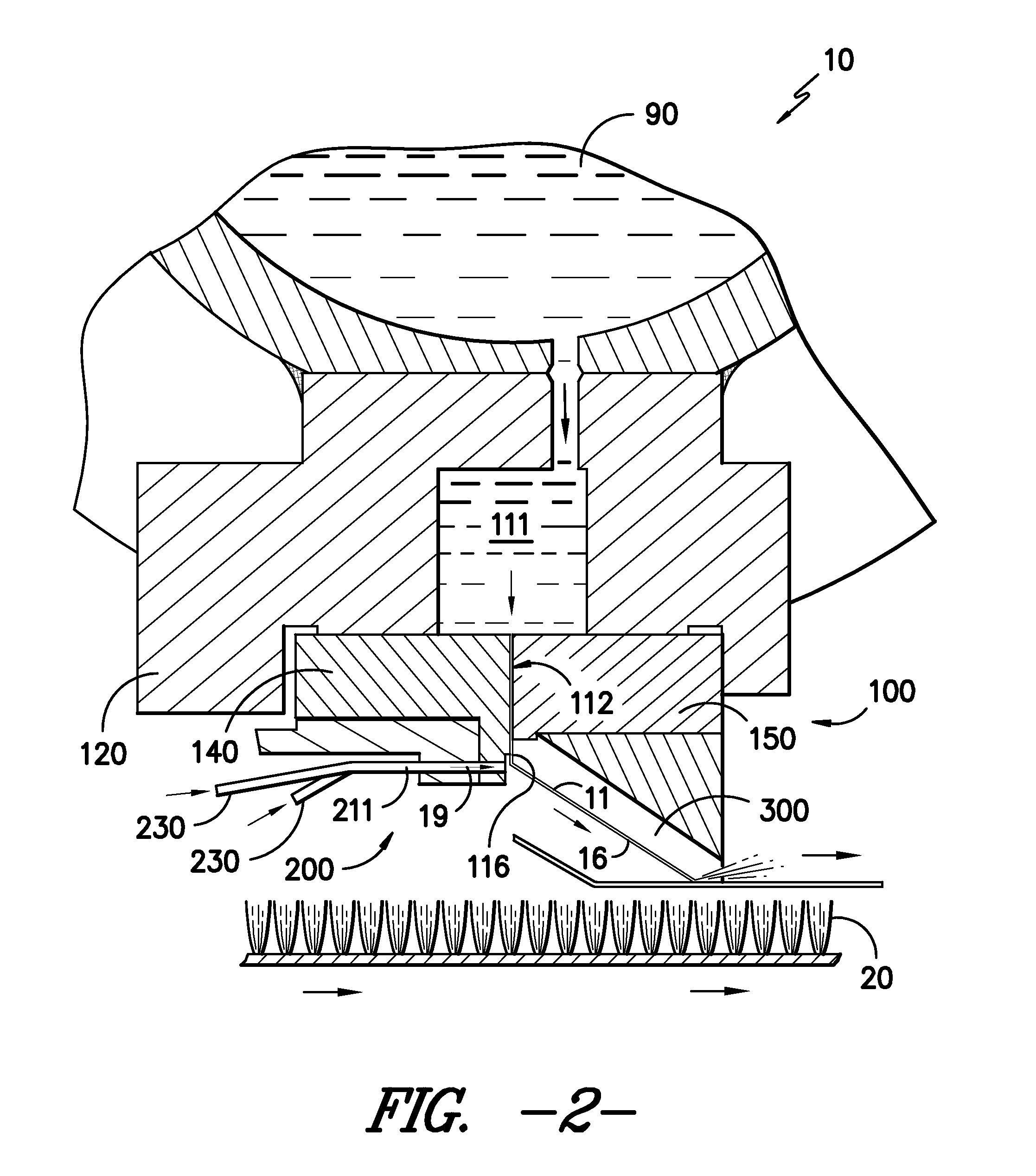
[0020]Reference will now be made to the drawings, wherein to the extent possible, like reference numerals designate like characters throughout the various views. Referring now to FIGS. 1 and 2, there is shown a cross-sectional view of an exemplary liquid-jet application system 10. As illustrated, the liquid-jet application system 10 generally includes a liquid jet module 100, an impingement jet module 200 and a collection module 300. A pressurized liquid supply 90, holding a liquid, such as an ink, dye, or the like, under pressure, provides the liquid to the liquid jet module 100. The pressurized liquid passes through the liquid jet module 100 and is emitted as pressurized, coherent liquid streams 11. As shown in FIG. 1, the liquid stream 11 may be applied as an undisrupted flow path 15 against the surface of a target substrate 20. In the illustrated arrangement, the substrate 20 is a textile such as a carpet, pile fabric, or the like. However, it is likewise contemplated that the s...


PUM

PropertyMeasurementUnit
Lengthaaaaaaaaaa
Diameteraaaaaaaaaa

Abstract

An improved system for application of liquid streams to a substrate. The system incorporates open face flow channels for carrying the liquid away from fully enclosed flow segments prior to discharge along an unconstrained flow path. The present invention further provides an improved, self-aligning modular assembly for delivery of impingement jet to the liquid streams for diverting the direction of the liquid streams. The present invention further provides an improved arrangement for collection of the deflected liquid in response to application of the impingement jet without excess residue build-up.

Description

TECHNICAL FIELD[0001]The present invention relates generally to an apparatus and method for forming one or more liquid streams having relatively small, well defined cross sectional areas which are normally directed to a target substrate, and for selectively interrupting and redirecting the flow of such liquid streams by application of gaseous fluid impingement jets transverse to the normal flow direction of the liquid streams. More specifically, the invention relates to an apparatus and method providing precise and substantially instantaneous switching between (i) a normal application mode in which a liquid stream is applied to a substrate and (ii) a diversion mode in which the liquid stream is redirected away from the substrate. Such switching is carried out in response to commands to develop desired fine scale treatment patterns across the substrate.BACKGROUND OF THE INVENTION[0002]Systems that provide relatively fine scale treatment patterns of liquid across a target substrate by...

Claims


Application Information

Patent Timeline
IPC IPC(8): B05D1/02B05C11/00
CPCB05C5/027B05D1/02D06B1/02D06B11/0059B05B15/0431B05B1/267B05B1/28B05B15/0406B05B1/205B05B14/00B05B12/18
Inventor LOVE, III, FRANKLIN S.RUMLER, JOSEPH E.HORNUNG, MARK A.BRYANT, JAMES C.KOH-FALLET, SHARON E.
Owner LOVE III FRLIN S
Learn More