Fan assembly

Active Publication Date: 2012-02-09
DYSON TECH LTD
View PDF3 Cites 135 Cited by
  • Summary
  • Abstract
  • Description
  • Claims
  • Application Information

AI Technical Summary

Benefits of technology

[0011]The different air paths thus present within the fan assembly may be selectively opened and closed by a user to vary the temperature of the air flow emitted from the fan assembly. The fan assembly may include a valve, shutter or other means for selectively closing one of the air paths so that all of the air flow leaves the fan assembly through either the first air outlet(s) or the second air outlet(s). For example, a shutter may be slidable or otherwise moveable over the outer surface of the casing to selectively close either the first air outlet(s) or the second air outlet(s), thereby forcing the air flow either to pass through the heating means or to by-pass the heating means. This can enable a user to change rapidly the temperature of the air flow emitted from the casing.
[0037]The means for creating an air flow through the casing preferably comprises an impeller driven by a motor. This can provide a fan assembly with efficient air flow generation. The means for creating an air flow preferably comprises a DC brushless motor. This can avoid frictional losses and carbon debris from the brushes used in a traditional brushed motor. Reducing carbon debris and emissions is advantageous in a clean or pollutant sensitive environment such as a hospital or around those with allergies. While induction motors, which are generally used in bladed fans, also have no brushes, a DC brushless motor can provide a much wider range of operating speeds than an induction motor.

Problems solved by technology

A disadvantage of this type of arrangement is that the air flow produced by the rotating blades of the fan heater is generally not uniform.
These variations result in the generation of a turbulent, or ‘choppy’, air flow which can be felt as a series of pulses of air and which can be uncomfortable for a user.
A further disadvantage resulting from the turbulence of the air flow is that the heating effect of the fan heater can diminish rapidly with distance.
It is undesirable for parts of the appliance to project outwardly, or for a user to be able to touch any moving parts, such as the blades.
Fan heaters tend to house the blades and the heat radiating coils within a cage or apertured casing to prevent user injury from contact with either the moving blades or the hot heat radiating coils, but such enclosed parts can be difficult to clean.
Consequently, an amount of dust or other detritus can accumulate within the casing and on the heat radiating coils between uses of the fan heater.
When the heat radiating coils are activated, the temperature of the outer surfaces of the coils can rise rapidly, particularly when the power output from the coils is relatively high, to a value in excess of 700° C. Consequently, some of the dust which has settled on the coils between uses of the fan heater can be burnt, resulting in the emission of an unpleasant smell from the fan heater for a period of time.

Method used


Image

  • Fan assembly
  • Fan assembly
  • Fan assembly

Examples


Embodiment Construction

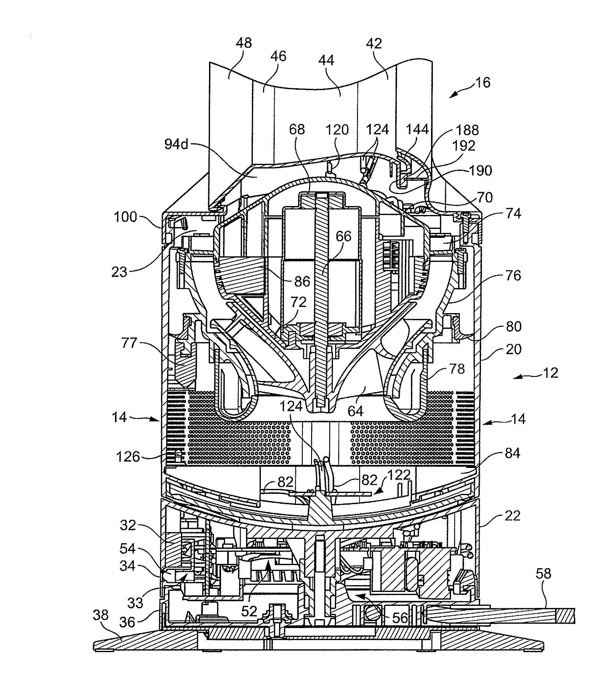
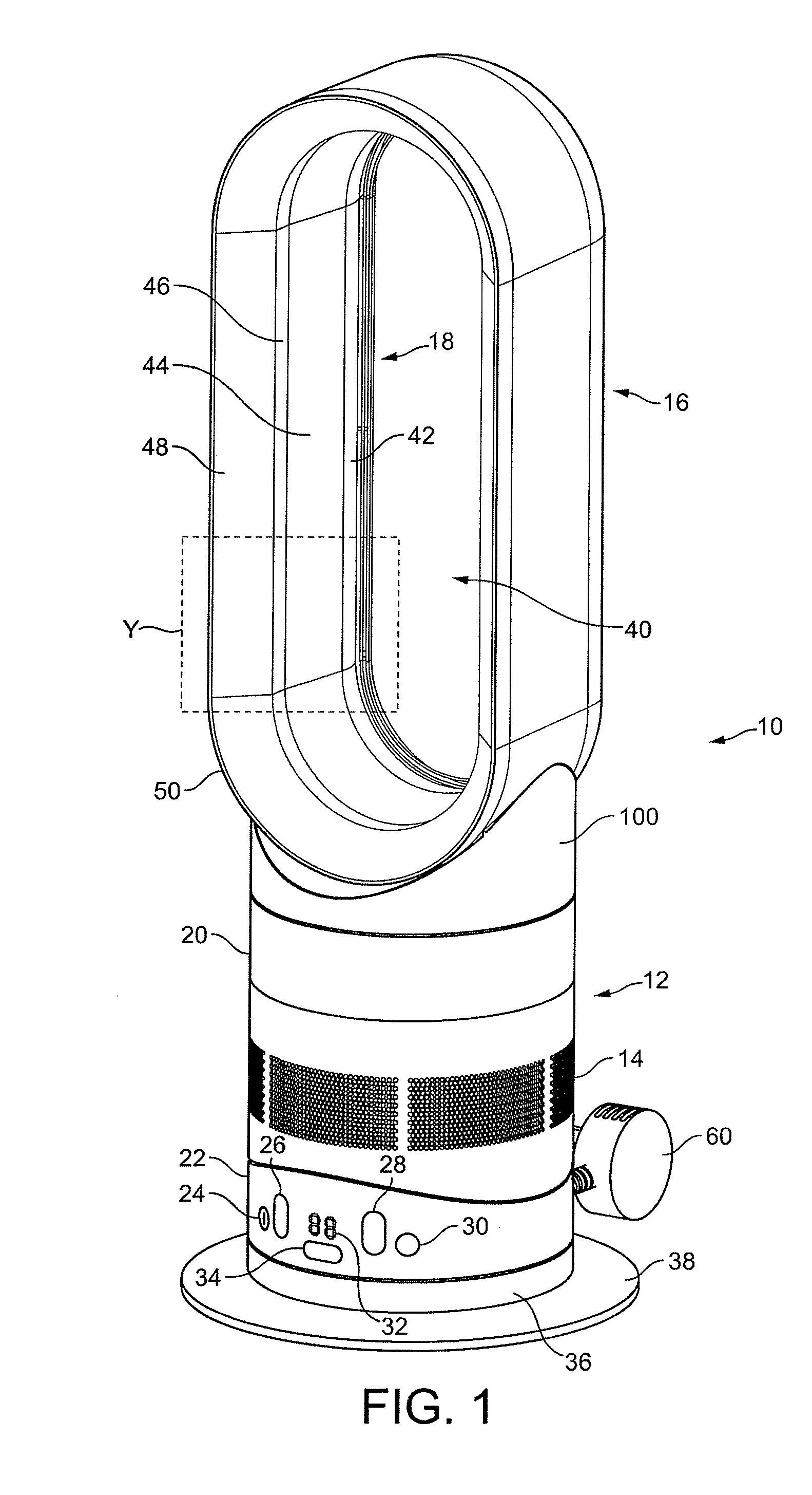
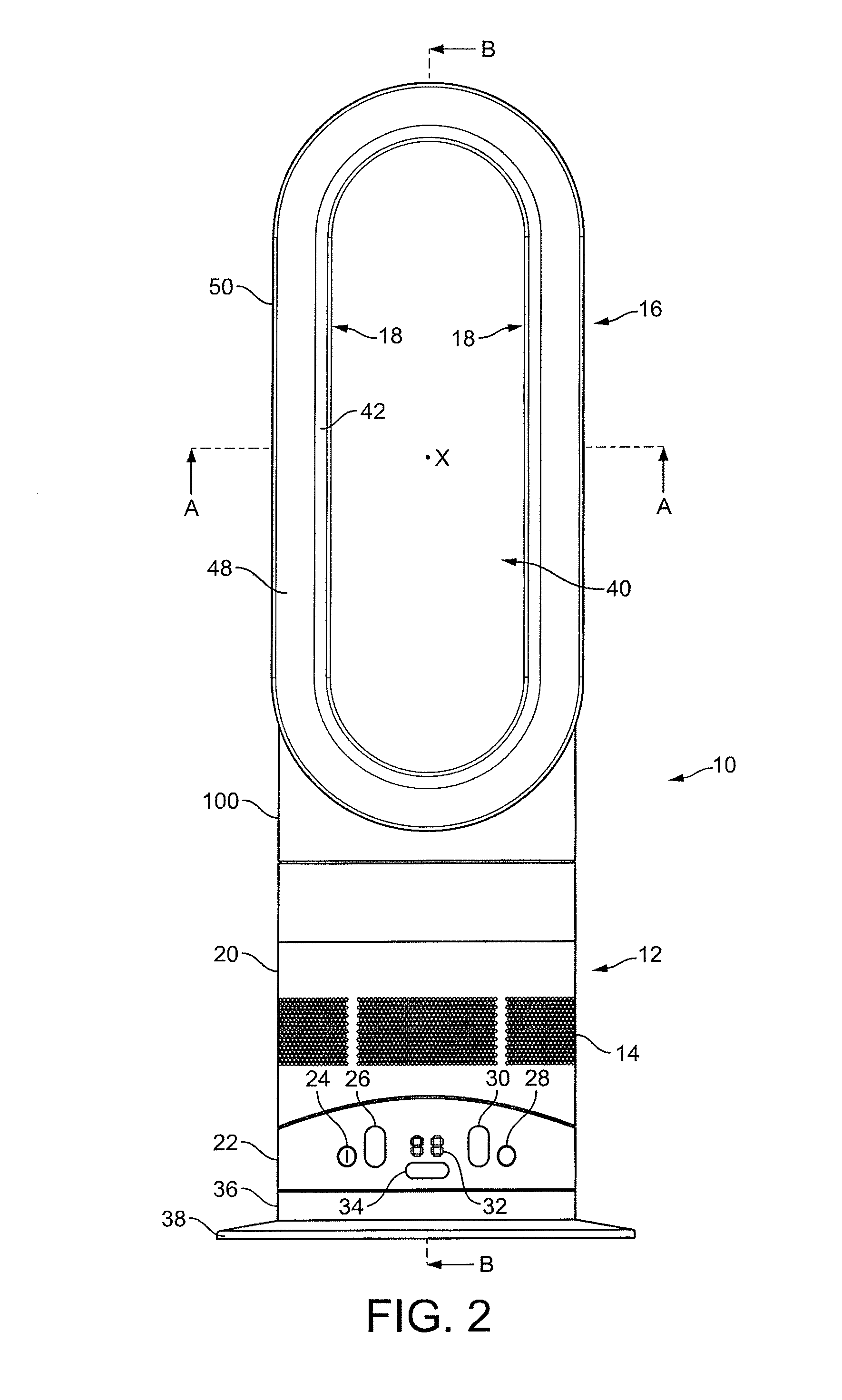
[0055]FIGS. 1 and 2 illustrate external views of a fan assembly 10. The fan assembly 10 is in the form of a portable fan heater. The fan assembly 10 comprises a body 12 comprising an air inlet 14 through which a primary air flow enters the fan assembly 10, and a nozzle 16 in the form of an annular casing mounted on the body 12, and which comprises at least one air outlet 18 for emitting the primary air flow from the fan assembly 10.

[0056]The body 12 comprises a substantially cylindrical main body section 20 mounted on a substantially cylindrical lower body section 22. The main body section 20 and the lower body section 22 preferably have substantially the same external diameter so that the external surface of the upper body section 20 is substantially flush with the external surface of the lower body section 22. In this embodiment the body 12 has a height in the range from 100 to 300 mm, and a diameter in the range from 100 to 200 mm.

[0057]The main body section 20 comprises the air ...


PUM


Abstract

A fan assembly includes a motor-driven impeller for creating an air flow, at least one heater for heating a first portion of the air flow, means for diverting a second portion of the air flow away from said at least one heater, and a casing comprising at least one first air outlet for emitting the first portion of the air flow and at least one second air outlet from emitting the second portion of the air flow. To cool an external surface of the casing, at least one second air outlet is arranged to direct at least part of the second portion of the air flow over the external surface.

Description

REFERENCE TO RELATED APPLICATIONS[0001]This application claims the priority of United Kingdom Application No. 1013265.2, filed Aug. 6, 2010, the entire contents of which are incorporated herein by reference.FIELD OF THE INVENTION[0002]The present invention relates to a fan assembly. In a preferred embodiment, the present invention relates to a fan heater for creating a warm air current in a room, office or other domestic environment.BACKGROUND OF THE INVENTION[0003]A conventional domestic fan typically includes a set of blades or vanes mounted for rotation about an axis, and drive apparatus for rotating the set of blades to generate an air flow. The movement and circulation of the air flow creates a ‘wind chill’ or breeze and, as a result, the user experiences a cooling effect as heat is dissipated through convection and evaporation.[0004]Such fans are available in a variety of sizes and shapes. For example, a ceiling fan can be at least 1 m in diameter, and is usually mounted in a ...

Claims


Application Information

Patent Timeline
IPC IPC(8): F04B39/06F04B53/08
CPCF04D15/0218F24F7/007F24F13/06F24F2013/205F24F2221/12F24F2221/28F24H2250/04F04F5/16F24H3/0411F24H3/0417F24H9/0063F24H9/1872F24F2221/34F04D25/08Y10T137/6525Y10T137/6552F24H3/12F04D29/44
Inventor WALLACE, JOHN DAVIDCHOONG, CHANG HIN
Owner DYSON TECH LTD
Why Eureka
Try Eureka