
Media cartridge with shifting ribs

a technology of media cartridges and ribs, which is applied in the direction of typewriters, printing, inking apparatus, etc., can solve the problems and achieve the effect of reducing the likelihood of media or ink ribbon being snagged and/or damaged

Active Publication Date: 2012-02-02
BRADY WORLDWIDE INC
View PDF6 Cites 118 Cited by
  • Summary
  • Abstract
  • Description
  • Claims
  • Application Information

AI Technical Summary

Benefits of technology

[0009]In some forms, the centering the length of media and the ribbon at the position of initial insertion may thereby inhibit contact of the length of media and the ink ribbon with the print head and the platen roller. Among other things, centering the media and ink ribbon may prevent interference of the media and ink ribbon with the components of a printer and therefore reduces the likelihood of the media or ink ribbon being snagged and / or damaged.
[0010]In another form, the shifting ribs may include a first shifting rib on one side of the cartridge housing and a second shifting rib on an opposing side of the cartridge housing. The first shifting rib may be a tab configured to engage a corresponding slot formed at a lower end of a wall of the cartridge receptacle. During insertion, an interaction of the tab with the wall of the cartridge receptacle above the slot may initially center the length of media and the ribbon between the platen roller and the print head before the tab engages the slot. After a position of insertion at which the tab engages the slot, an engagement of the tab with the slot may permit the shifting of the length of media and the ribbon toward one of the print head and the platen roller. The second shifting rib may be an angled rib configured for engagement with a wall of the cartridge receptacle. Upon insertion, engagement of the angled rib with the wall of the cartridge receptacle may shift the length of media and the ink ribbon toward one of the print head and the platen roller. The second shifting rib may be configured to not bias the length of media and ribbon toward one of the print head and the platen roller until the first shifting rib engages the slot.
[0015]Accordingly, a media cartridge and printer assembly are disclosed that offer improved loading of the media cartridge into a printer and, more specifically, minimizes the possibility of damage to either the media or the ink ribbon during loading. As will be described in further detail below, preventing damage to the media and ink ribbon is achieved by placing shifting rib(s) on the media cartridge that direct the cartridge in such a manner as to avoid snagging or catching the media and ribbon on the printer components (i.e., the print head, the platen roller, the heat sink, etc.) during loading.

Problems solved by technology

Among other things, centering the media and ink ribbon may prevent interference of the media and ink ribbon with the components of a printer and therefore reduces the likelihood of the media or ink ribbon being snagged and / or damaged.

Method used


Image

  • Media cartridge with shifting ribs
  • Media cartridge with shifting ribs
  • Media cartridge with shifting ribs

Examples


Embodiment Construction

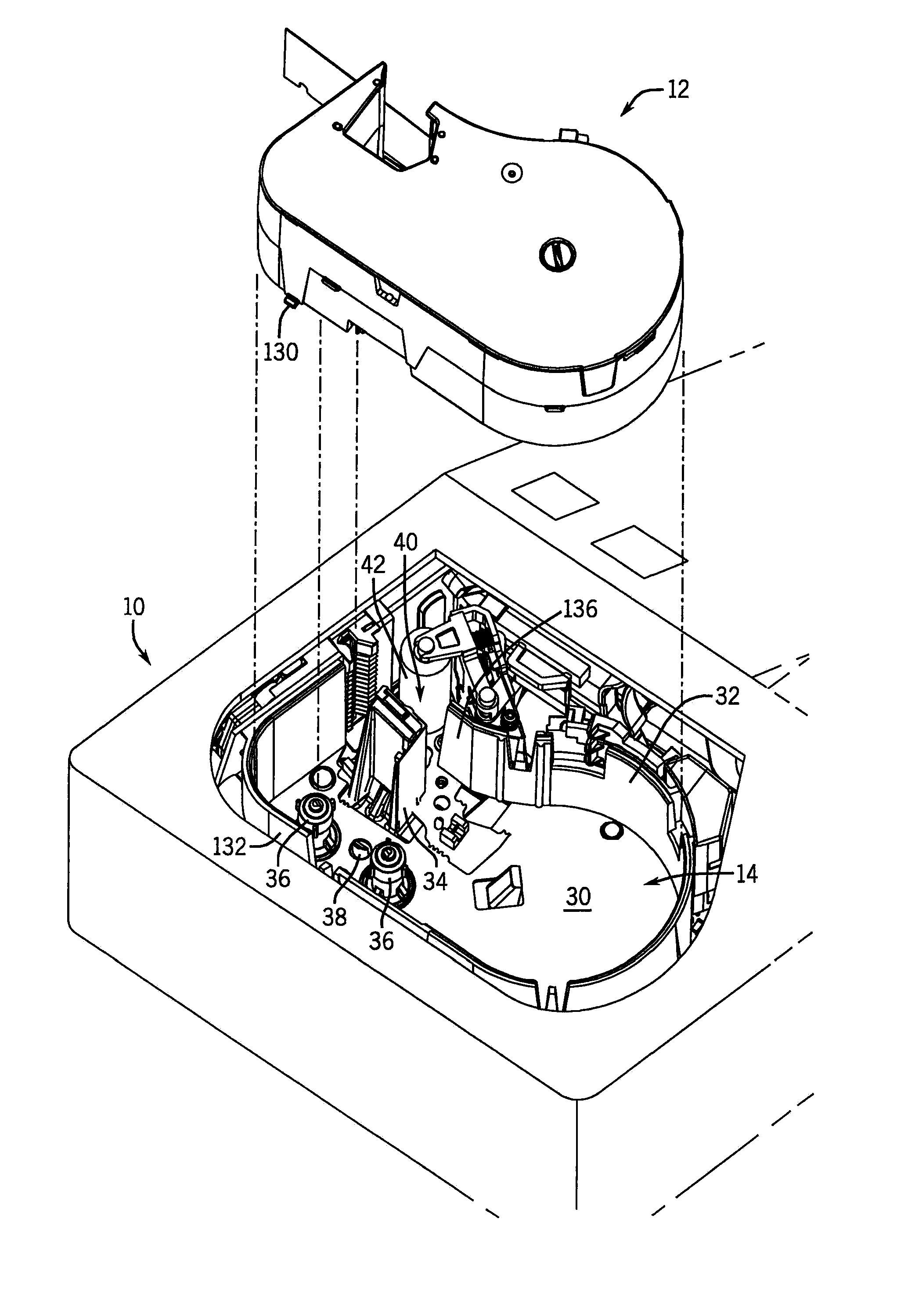
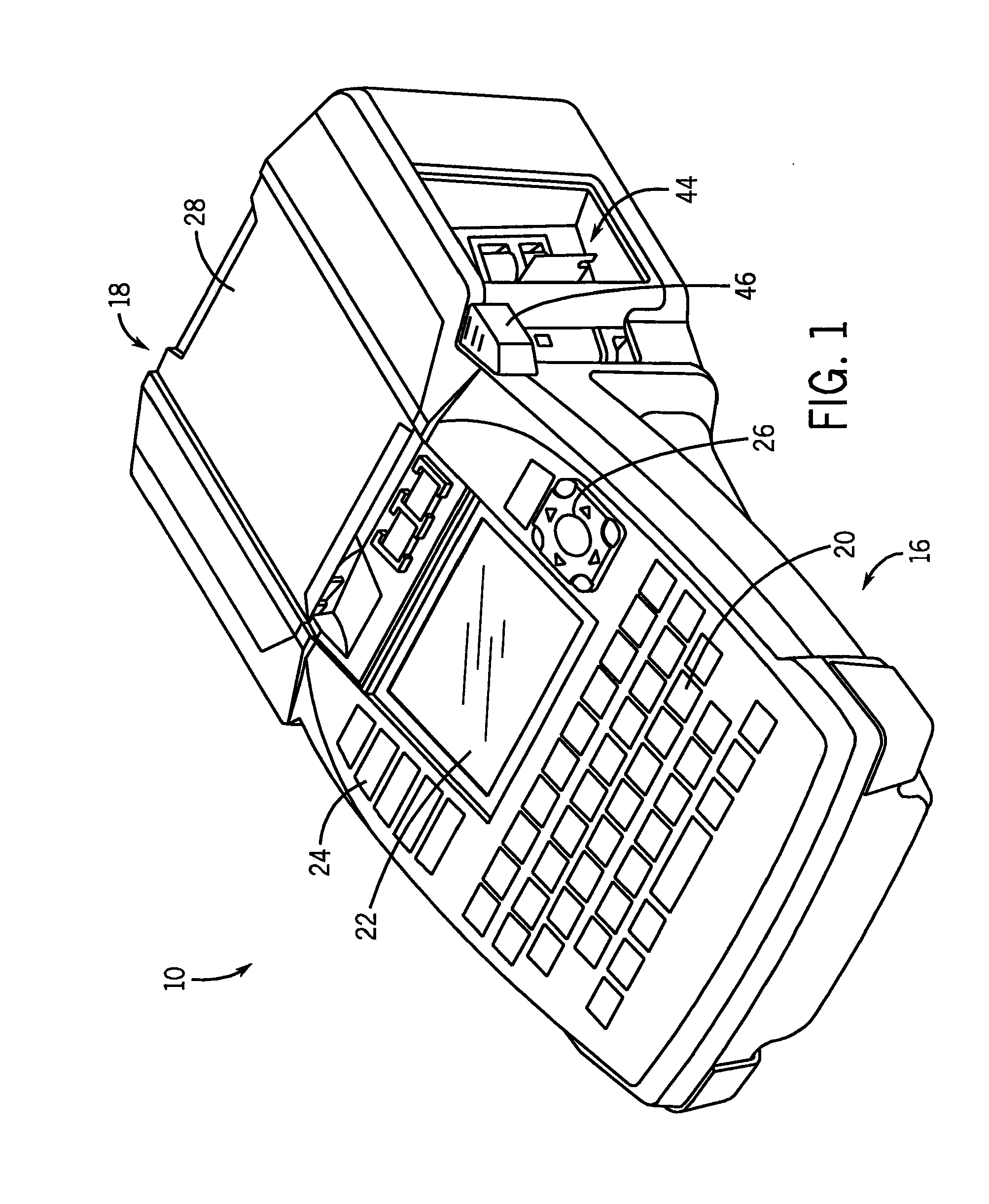
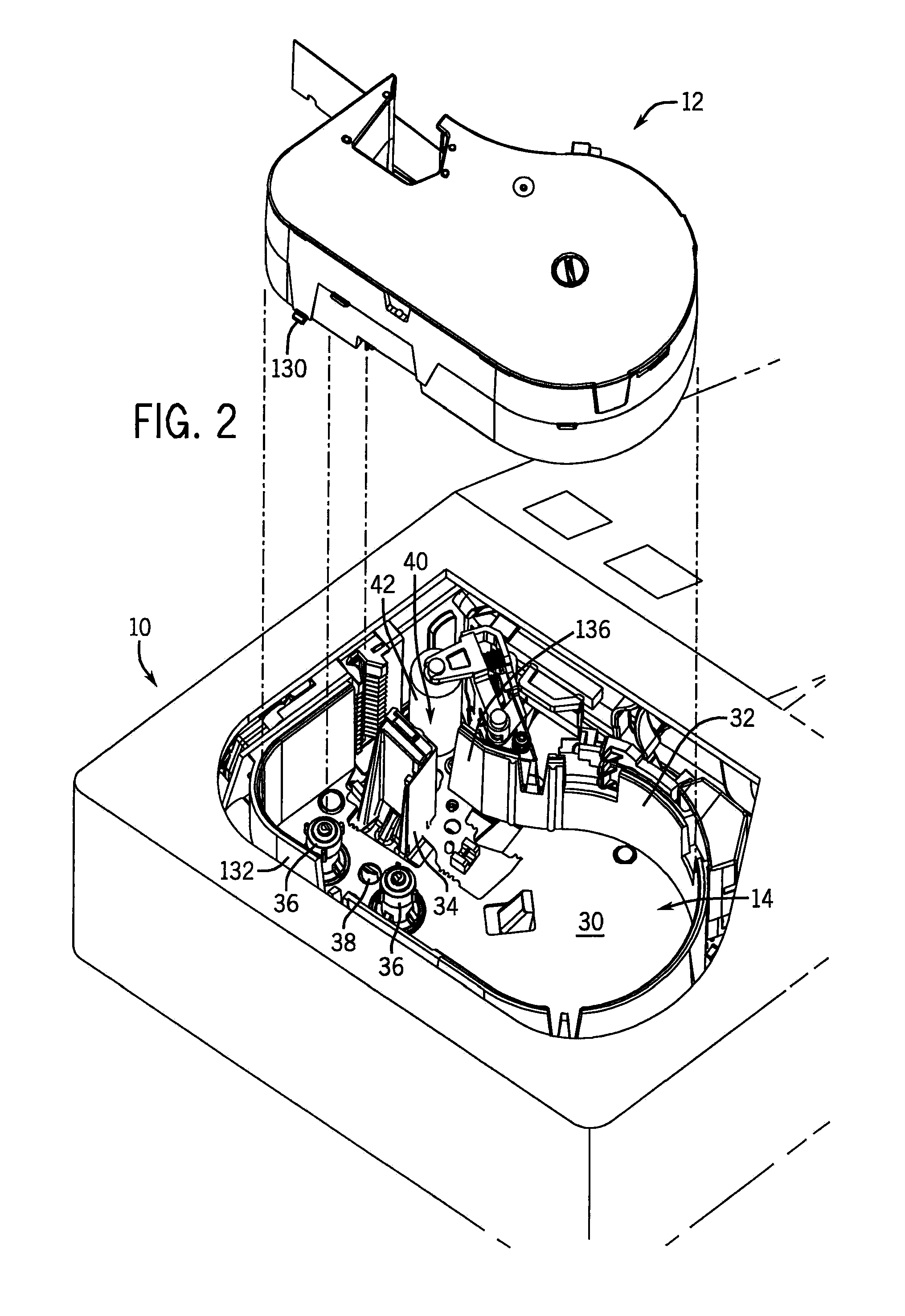
[0042]Referring first to FIG. 1, a printer 10 is shown. The printer 10 is of a type that is a portable handheld printer for use at any of a number of locations and can also be placed on a table top for stationary use. In FIGS. 2 and 3, the printer 10 is shown receiving a media cartridge 12 in a cartridge receptacle 14 of the printer 10. Those having ordinary skill in the art will appreciate that although the printer 10 is shown as being a particular kind of printer, that the features described herein with respect to the media cartridge 12 and the printer 10 are applicable to any number of kinds of cartridge-receiving printers.

[0043]The printer 10 of FIG. 1 includes a body 16 with a head 18 located at one end thereof. The body 16 supports a number of items including a keypad 20 for the entry of data, a display 22 positioned between the keypad 20 and the head 18 of the printer 10, a row of buttons 24 on one lateral side of the display 22, and a navigational keypad 26 on the other late...


PUM


Abstract

A media cartridge is disclosed for insertion into a cartridge receptacle of a printer. The media cartridge includes a cartridge housing having one or more shifting ribs on the cartridge housing. At a position of initial insertion of the media cartridge into the cartridge receptacle, the shifting ribs are configured to center a length of media and an ink ribbon of the media cartridge between a print head and a platen roller in the cartridge receptacle. As the insertion of the media cartridge into the cartridge receptacle continues, the shifting ribs shift the length of media and the ink ribbon toward one of the print head and the platen roller.

Description

CROSS-REFERENCE TO RELATED APPLICATIONS[0001]Not applicable.STATEMENT OF FEDERALLY SPONSORED RESEARCH OR DEVELOPMENT[0002]Not applicable.BACKGROUND OF THE INVENTION[0003]This disclosure relates to a media cartridge for a printer. In particular, this disclosure relates to improvements in the loading of the media cartridge into the printer.[0004]Many printers are designed to receive cartridges that provide a length of media for printing. These media cartridges are often constructed so that a leading end of the media is pre-positioned for insertion between the components of the printing mechanism (e.g., the print head and platen roller) during the loading of the cartridge into the printer. This type of positioning of the media during the loading of the cartridge is generally preferable to, for example, requiring a user to manually thread an end of the media between the printing components in a cartridge-less type construction.[0005]Even with this pre-positioning of the media, it is pos...

Claims


Application Information

Patent Timeline
IPC IPC(8): B41J35/28
CPCB41J3/36B41J17/32B41J35/28B41J15/044
Inventor SUVA, ALAN J.CARRIERE, RICHARD L.
Owner BRADY WORLDWIDE INC
Learn More