
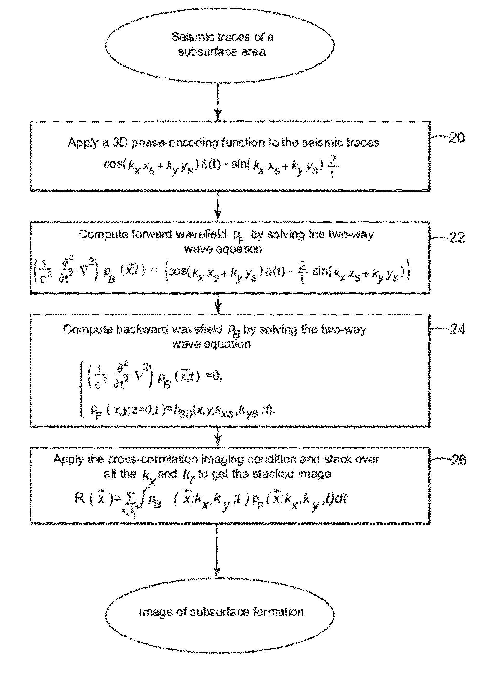
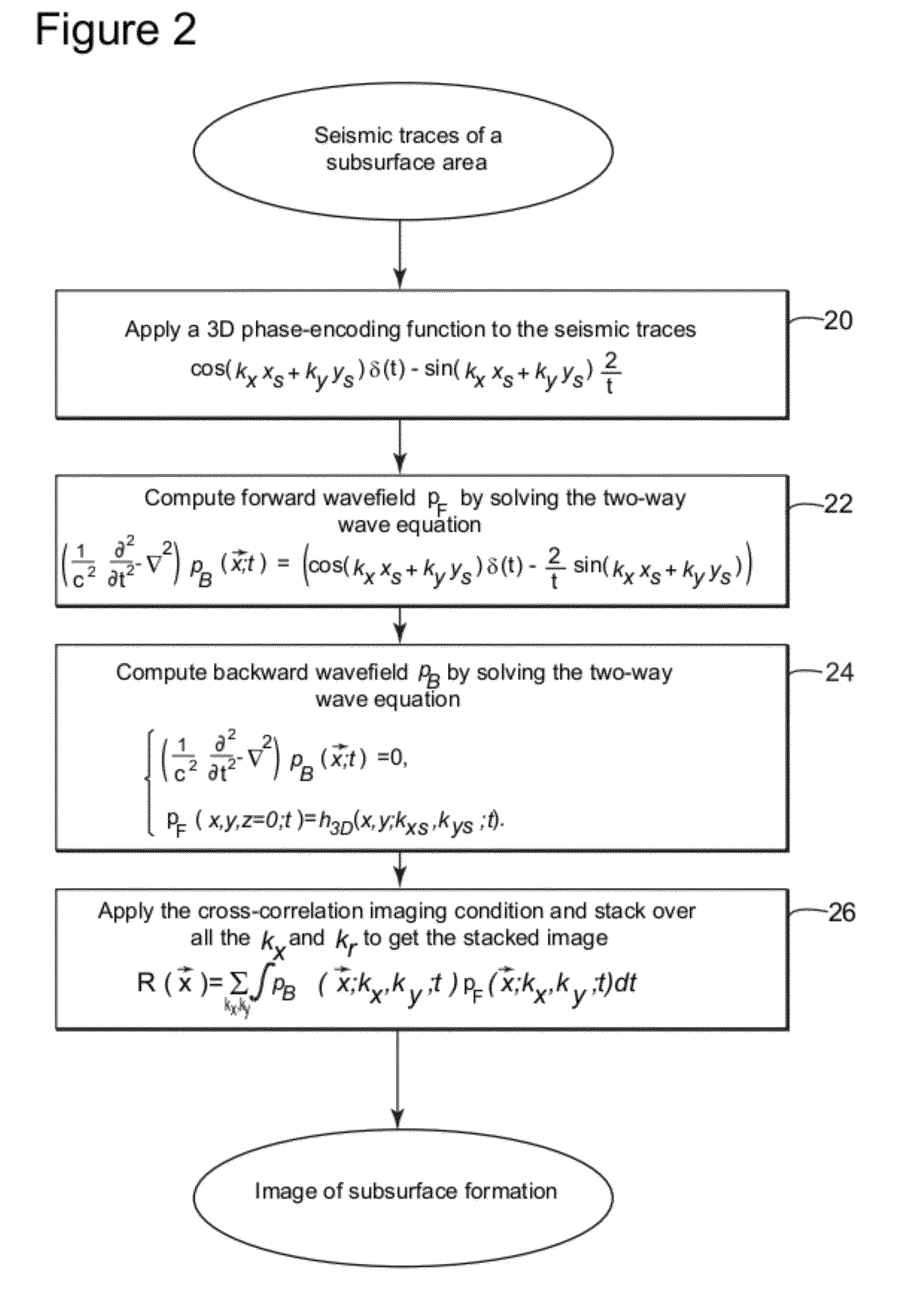
3-d harmonic-source reverse time migration systems and methods for seismic data analysis

a reverse time migration and harmonic source technology, applied in the field of geophysics, can solve the problems of inapplicability to complex situations, inability to address complex non-horizontal features of current migration methods, and high computational power of rtm, and achieve the effect of improving systems and methods

Active Publication Date: 2012-02-02
CGGVERITAS SERVICES
View PDF3 Cites 22 Cited by
  • Summary
  • Abstract
  • Description
  • Claims
  • Application Information

AI Technical Summary

Benefits of technology

[0020]One object of the invention is to provide enhanced ...

Problems solved by technology

Further, current migration methods do not have the capability to address complex non-horizontal features of the formation, including steeply dipping reflectors such as salt flanks.
These techniques become inapplicable for complex situations because the integrity of these wave equation approximations breaks down as the dip angle goes beyond 70 degrees.
In practice, however, RTM requires significantly more computational power than other techniques, which can be very costly, especially when applied to a TTI (Tilted Transverse Isotropy) project.
As such, the cost to run the RTM algorithms may, often times, outweigh the benefits that RTM processing provides.
There are, however, disadvantages to applying RTM to seismic traces using the conventional two-way acoustic wave equation.
One of the disadvantages is the amount of computational power required to apply such algorithms.
Other known methods such as phase encoding and delayed-shot migration and plane-wave migration do not address these problems as phase encoding is dependent on stacking power to remove the cross-talk artifacts and the delayed-shot and plane wave migration methods required expensive computation for RTM.
On the other hand, for other known migration techniques such as common-shot migration, the migration aperture is limited in both directions and may fail to image the dipping events in far offsets.

Method used


Image

  • 3-d harmonic-source reverse time migration systems and methods for seismic data analysis
  • 3-d harmonic-source reverse time migration systems and methods for seismic data analysis
  • 3-d harmonic-source reverse time migration systems and methods for seismic data analysis

Examples


Embodiment Construction

[0029]The present disclosure is directed to a method and system for efficiently providing high quality seismic data processing using 3-D harmonic-source reverse time migration. Further, the various embodiments of the present invention can be implemented via computer-executable instructions, various elements of embodiments of the present invention are in essence the software code defining the operations of such various elements. Also, the embodiments of the present invention may be implemented in a controller or processor as will be discussed later. The executable instructions or software code may be obtained from a readable medium (e.g., a hard drive media, optical media, EPROM, EEPROM, tape media, cartridge media, flash memory, ROM, memory stick, and / or the like) or communicated via a data signal from a communication medium (e.g., the Internet). In fact, readable media can include any medium that can store or transfer information.

[0030]Seismic data is generally displayed in the for...


PUM


Abstract

Computing device and method for processing seismic traces to produce an image of a subsurface area. The method includes receiving a series of seismic traces related to the subsurface area and recorded by one or more seismic receivers, wherein the one or more seismic sources are originally generated by a source; applying a phase encoding function to the series of seismic traces, at least a portion of said seismic traces comprise signals reflected by geological interfaces of the subsurface area; applying a 3 dimensional (3D) harmonic-source reverse time migration of the series of seismic traces encoded with the phase encoding function; computing a forward wavefield by solving a first wave equation; computing a backward wavefield by solving a second wave equation; and cross-correlating the forward wavefield with the backward wavefield to generate an image of the subsurface.

Description

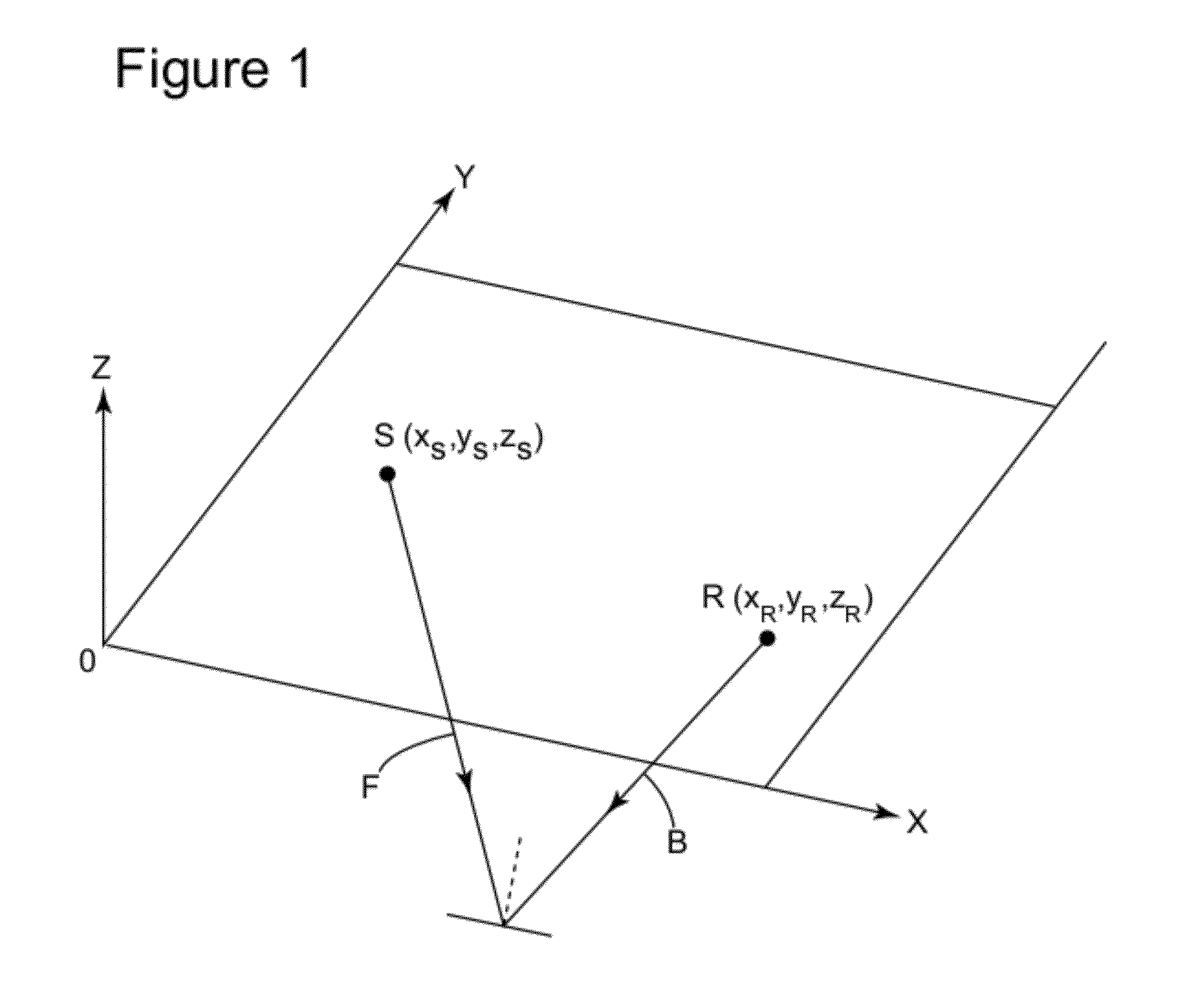
CROSS REFERENCE TO RELATED APPLICATION[0001]This Non-Provisional application claims priority under 35 U.S.C. §119(e) on U.S. Provisional Application No. 61 / 368,456 filed on Jul. 28, 2010, the entire contents of which are hereby incorporated by reference into the present application.TECHNICAL FIELD[0002]The present disclosure relates generally to geophysics and, in particular, methods and systems for seismic data analysis. More specifically, the present disclosure concerns using 3-D harmonic source reverse time migration.BACKGROUND OF THE INVENTION[0003]In the oil and gas industry, one widely used technique to search for oil and / or gas is to conduct seismic surveys to study subsurface formations. Typically, in seismic surveys, geophysicists use “seismic reflection” techniques to produce an image of the subsurface formations. These techniques generally involve emitting acoustic signals from a seismic energy source that propagate into the earth and recording the signals that are at lea...

Claims


Application Information

Patent Timeline
IPC IPC(8): G01V1/36
CPCG01V1/282G01V2210/679G01V2210/74G01V2210/51G01V2210/675G01V1/345
Inventor SOUBARAS, ROBERTZHANG, YU
Owner CGGVERITAS SERVICES
Learn More