Surgical Tool with Crossbar Lever

Inactive Publication Date: 2012-01-26
CONMED CORP
View PDF5 Cites 204 Cited by
  • Summary
  • Abstract
  • Description
  • Claims
  • Application Information

AI Technical Summary

Benefits of technology

[0010]The present invention creates an enhanced degree and ease of control over the manipulation of a surgical tool of the type which has a lever which is pivoted relative to a handgrip of a handle assembly. The present invention involves the use of a lever which has a T-shaped crossbar extending at the front of the lever. The surgeon extends his or her middle two fingers on opposite sides of a bridge or leg portion of the T-shaped crossbar. Locating the two middle fingers on opposite sides of the bridge portion of the crossbar allows the surgeon to apply positive firm contact with the lever and achieve a greater degree of precision in manipulation than is possible when all four fingers of the surgeon's fingers are located within the center of the relatively large oval opening prior art lever. The better contact with the lever also stabilizes the surgical tool against inadvertent movement. A foreword transverse portion of the T-shaped lever is available for the surgeon to contact with opening finger movement in order to assist in moving the jaws away from one another. The forward transverse portion of the T-shaped lever is also available to give the surgeon the opportunity to change where on the crossbar lever the rearward squeezing force is applied by the fingers, when it is desired to apply a greater amount of squeezing force to compress the tissue between the jaws. The T-shaped crossbar lever also offers an ideal location for locating control buttons and switches for easy contact by the fingers to control the delivery of electrical energy during use of the tool.

Problems solved by technology

Coaptive tissue sealing avoids the need to manually surture or tie-off vessels during a surgical procedure, which would be very difficult to perform in a minimally invasive procedure.
Sealing blood vessels is of particular concern, because a failed vessel seal after the conclusion of surgery leads to internal bleeding.
Internal bleeding usually requires a second operation to gain access to and seal the leaking vessel, which induces further trauma and risk to the patient.
However, since the handgrip is not entirely enclosed or surrounded by the hand and the fingers which extend to the lever, the handle assembly is somewhat loosely positioned in the surgeon's hand until the lever is grasped and pivoted.

Method used


Image

  • Surgical Tool with Crossbar Lever
  • Surgical Tool with Crossbar Lever
  • Surgical Tool with Crossbar Lever

Examples


Embodiment Construction

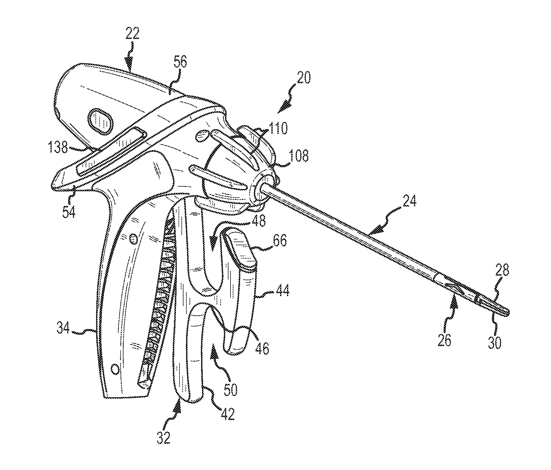
[0029]A surgical tool 20 which is useful in performing minimally invasive surgical procedures and which incorporates the present invention, is shown in FIG. 1. The surgical tool 20 includes a handle assembly 22, a shaft assembly 24 connected to the handle assembly, a jaw movement mechanism 26 located at a forward or front end of the shaft assembly 24, and jaws 28 and 30 connected to and moved by the jaw movement mechanism 26.

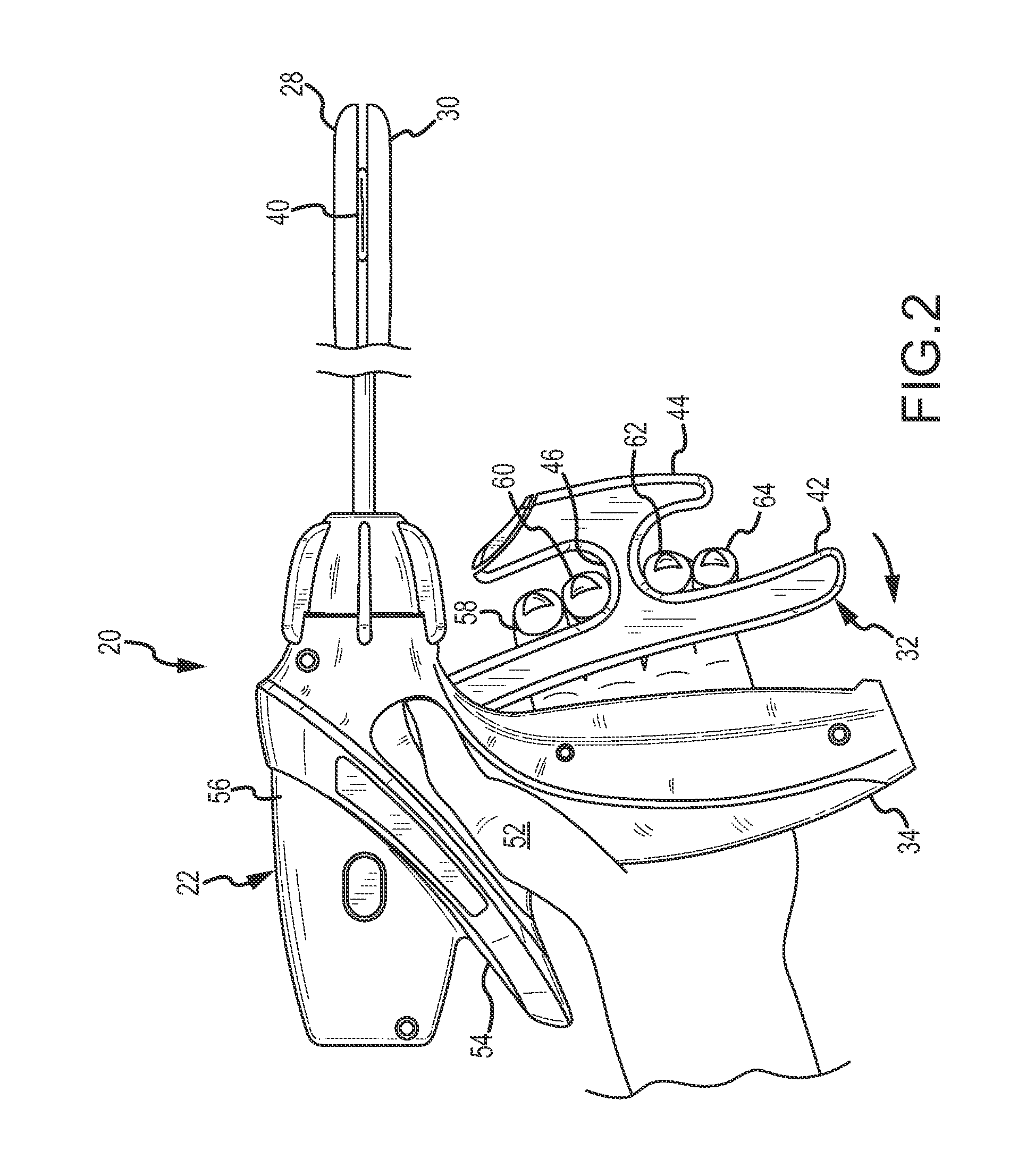
[0030]A movable crossbar lever 32 of the handle assembly 22 pivots relative to a fixed handgrip 34, as shown in FIGS. 2-4. The fixed handgrip 34 is contacted by the heel and thumb of the surgeon's hand, and the four fingers of the surgeon's hand extend to contact and squeeze the crossbar lever 32. An internal operating mechanism 36 (FIGS. 6-8) within the handle assembly 22 converts the relative pivoting movement of the lever 32 and handgrip 34 into relative longitudinal reciprocating movement of relatively movable shaft members of the shaft assembly 24. The long...


PUM


Abstract

A crossbar lever of a surgical tool has a bridge portion which extends forward and a transverse portion. The bridge portion is retained between the second and third fingers of the surgeon's hand, and this retention establishes greater control and stability of the surgical tool. The crossbar lever pivots relative to a handgrip of a handle assembly and a shaft assembly extends from the handle assembly. Tissue contacting or manipulating devices such as jaws are located at the forward end of the shaft assembly. The surgical tool is particularly useful in performing minimally invasive surgical procedures.

Description

CROSS REFERENCE TO RELATED INVENTIONS[0001]This application is related to U.S. patent application Ser. No. (24.373), titled Jaw Movement Mechanism and Method for Surgical Tool, and to U.S. patent application Ser. No. (24.376), titled Tissue Fusion System and Method for Performing a Self Test, and to U.S. patent application Ser. No. (24.377), titled Tissue Fusion System and Method of Performing a Functional Verification Test, all of which were filed concurrently herewith and assigned to the assignee hereof. The subject matter of these related patent applications are incorporated herein by this reference.FIELD OF THE INVENTION[0002]This invention relates to surgical tools used to grasp or compress tissue between a pair of jaws. More particularly, the present invention relates to a new and improved surgical tool having a crossbar lever which permits greater surgeon control during use of the surgical tool.BACKGROUND OF THE INVENTION[0003]Specialized surgical tools are required for many ...

Claims


Application Information

Patent Timeline
IPC IPC(8): A61B17/28
CPCA61B17/2909A61B18/1445A61B19/30A61B2018/145A61B2017/292A61B2018/0063A61B2017/00424A61B90/03
Inventor SUGALSKI, ERICHOLVERSON, ERIKHOUGHTON, CHRISTOPHER
Owner CONMED CORP
Why Eureka
Try Eureka