Magnetic drive connection for a reel mower

a drive shaft and reel mower technology, applied in the direction of mowers, agricultural tools and machines, etc., can solve the problems of affecting the operation of the mower, the damage to the reel head can still occur, and the reel head is also susceptible to damage, so as to reduce the damage to the mower from such obstructions, the effect of precise vertical control of the mower assembly and convenient removal and installation

Inactive Publication Date: 2012-01-26
BUCHKO JEFFREY
View PDF0 Cites 12 Cited by
  • Summary
  • Abstract
  • Description
  • Claims
  • Application Information

AI Technical Summary

Benefits of technology

[0016]When an obstruction is encountered, the magnetic force holding the reel face to the drive face will be insufficient to maintain the connection, and the reel member and reel will stop rotating while the drive face and drive member continue to rotate, while both are maintained in alignment by the centering bulb rotating in the centering recess. Damage to the mower from such obstructions is thus reduced.
[0017]A mechanism can be provided to force the drive face along the shaft axis away from the reel face to break the magnetic connection when it is desired to remove the reel head. It is contemplated that providing a magnetic connection on both ends of the reel shaft will better provide for convenient removal and installation, and provide the added benefit of providing the option to drive the reel head from either side such that configuring larger mower units with a considerable number of individual mower assemblies will be more readily accomplished. An embodiment is also disclosed that includes a magnetic connection on only one end of the reel head.
[0018]Vertical adjustment of the mower assembly with respect to the ground is provided by a linkage connecting the front and rear ground rollers of the assembly. A single screw controls the linkage to move the rollers closer together or further apart to adjust the vertical position of the mower assembly with respect to the ground. In one version of the linkage the front and rear rollers are moved closer together to move the mower assembly down closer to the ground. With the front and rear rollers closer together at the lower positions, more precise vertical control of the mower assembly is provided.

Problems solved by technology

Such reel mowers are more expensive and require more maintenance than rotary mowers, however they are preferred by golf courses and the like where appearance and healthy grass are important.
The reel head is also susceptible to damage when a rock or like object becomes jammed between the bed knife and one of the reel knives, since conventionally the reel head and bed knife are fixed to the frame, and so neither can move in response to the force of a jammed object.
Damage to the reel head can still occur however if, for example, the object jams between the bed bar, which is still rigidly attached to the frame, and the reel knives.

Method used


Image

  • Magnetic drive connection for a reel mower
  • Magnetic drive connection for a reel mower
  • Magnetic drive connection for a reel mower

Examples


Embodiment Construction

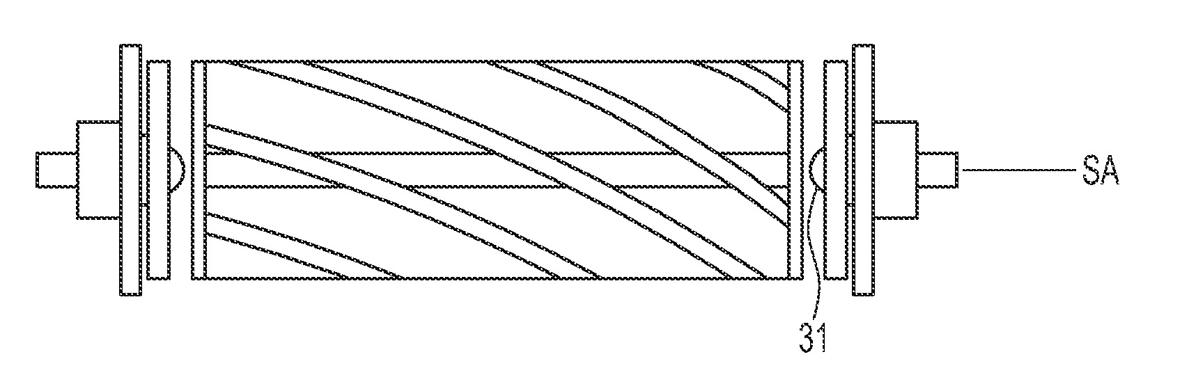
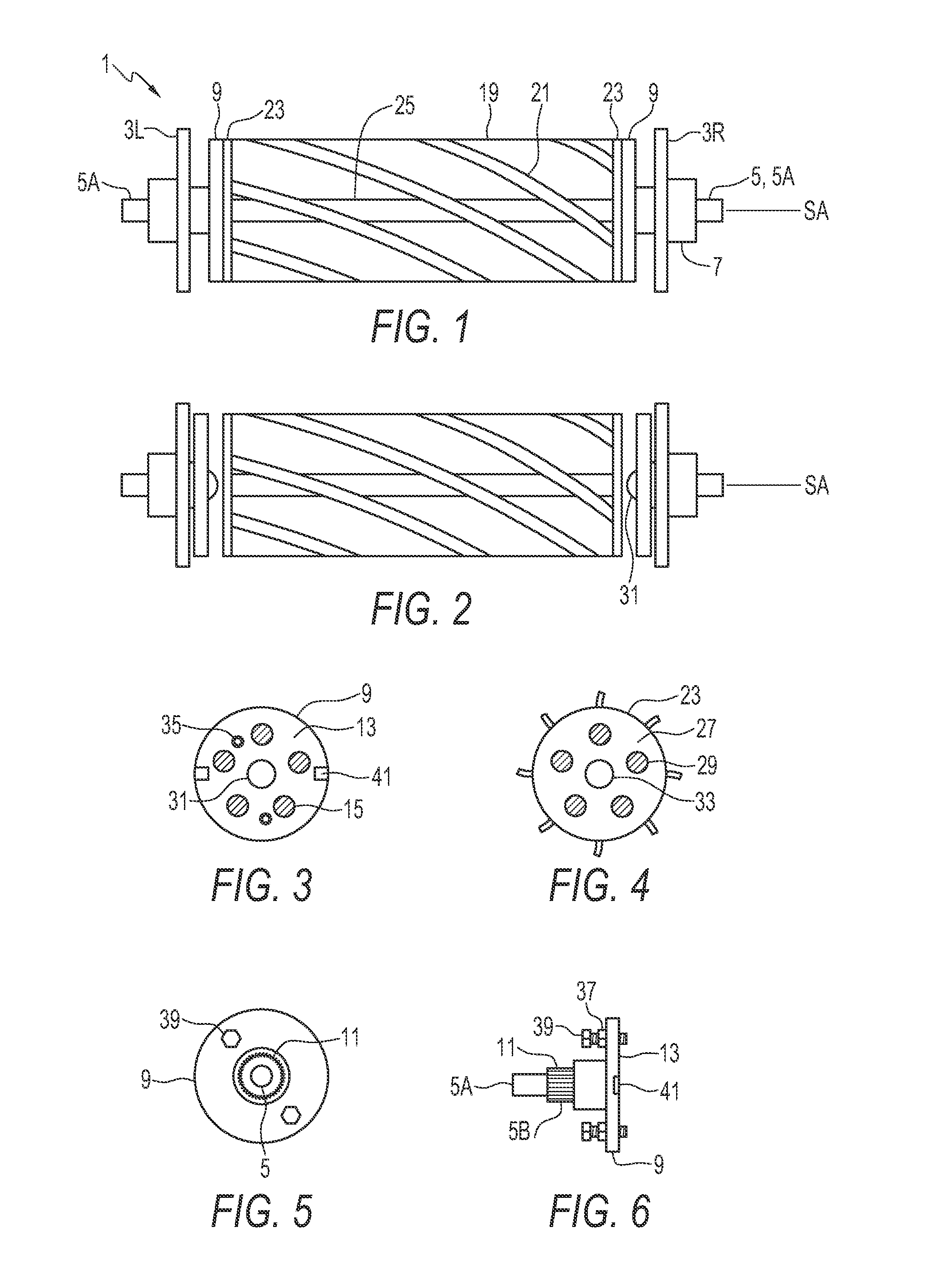
[0036]FIGS. 1 and 2 schematically illustrate a reel mower assembly 1 comprising a frame with right and left side plates 3R, 3L, each defining shaft apertures therethrough. A bearing housing 7 is mounted over the shaft aperture in each side plate 3R, 3L, and a stub shaft 5 extends through the bearing housing 7 and shaft aperture, and engages a bearing mounted in the bearing housing such that the bearing and stub shaft rotate together, and such that the stub shaft 5 is supported substantially in alignment with a shaft axis SA. An outer end 5A of the stub shaft 5 is located outside the frame side plates 3R, 3L and is adapted to be rotated about the shaft axis SA by a drive mechanism. A belt pulley, chain, sprocket, gear, or the like is attached to the outer end 5A of one of the stub shafts 5, and is driven conventionally.

[0037]The inner end 5B of each stub shaft 5, as seen in FIG. 6, is located between the right and left side plates 3R, 3L, and a drive member 9 is attached to the inner...


PUM


Abstract

A rotating mechanical apparatus, such as would be used in a reel mower assembly, comprises a drive member rotatably mounted in a frame about a shaft axis. The drive member has a drive face. A driven member has a driven shaft rotatably supported in the frame about the shaft axis, and a driven face. A projection extends outward from one of the drive face and the driven face and into a corresponding recess in the other. Magnets force the drive face against the driven face such that the driven shaft rotates with the drive member. One of the drive face and the driven face are movable along the shaft axis to disengage the projection from the recess. A height adjustment mechanism moves ground rollers closer together or farther apart to vary cutting height.

Description

CROSS-REFERENCE TO RELATED APPLICATIONS[0001]This application is a Continuation-in-Part of application Ser. No. 12 / 095,678, filed Oct. 2, 2006, currently pending, which is a National Stage of International Application PCT / CA06 / 01615, filed Oct. 2, 2006, expired, which claims priority to Provisional Patent Application No. 60 / 723,157, filed Oct. 3, 2005, expired.BACKGROUND[0002]This invention is in the field of driving shafts and in particular driving shafts for mower reels and the like via a magnetic connection.[0003]Reel mowers use a scissoring action to shear grass and like foliage, rather than tearing the leaves as with a conventional rotary mower. Because the shearing action leaves a neatly cut top end to the grass, compared to the torn end common with rotary cutters, the grass has an improved appearance. Such reel mowers are more expensive and require more maintenance than rotary mowers, however they are preferred by golf courses and the like where appearance and healthy grass a...

Claims


Application Information

Patent Timeline
Patent Type & Authority Applications(United States)
IPC IPC(8): A01D34/53
CPCA01D34/56
Inventor BUCHKO, JEFFREY
Owner BUCHKO JEFFREY
Why Eureka
Try Eureka