
Endoscopic Instrument

a technology of endoscopic instruments and control units, which is applied in the field of endoscopic instruments, can solve the problems of difficult implementation of parallel interfaces, difficult to provide image data processing units and control units for these sensors at the distal end of the endoscopic instrument, and limited space and power consumption

Active Publication Date: 2012-01-19
KARL STORZ GMBH & CO KG
View PDF12 Cites 23 Cited by
  • Summary
  • Abstract
  • Description
  • Claims
  • Application Information

AI Technical Summary

Benefits of technology

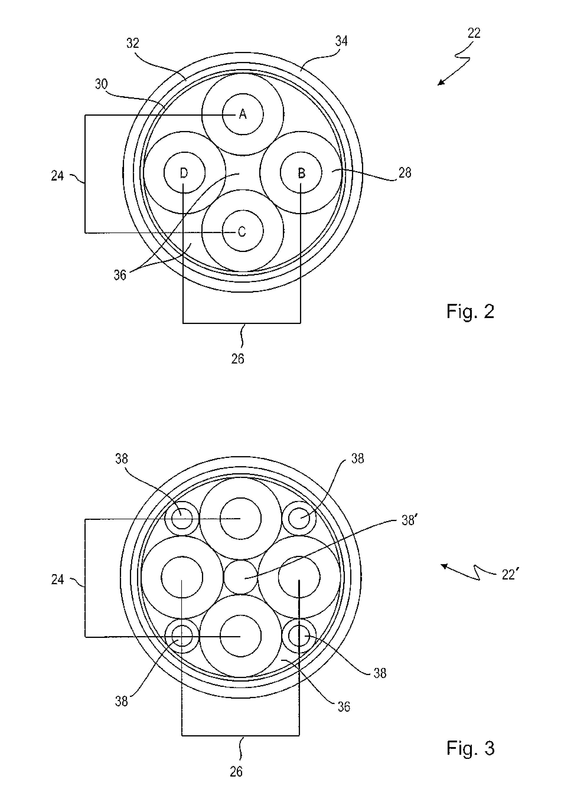
[0017]Using a data transmission element having a star quad arrangement, in particular embodied as a symmetric arrangement, may resolve the conflict present in endoscopic applications between the small outer dimensions and the high transmission quality and transmission bandwidth. A star quad cable arrangement may offer a compact structure in comparison to other data transmission elements and may offer a smaller attenuation when comparing same diameters. It is therefore possible to provide a good transmission quality at high resolutions of 1920×1080 pixels and a corresponding frame rate (30 / 60 Hz) also for endoscopic applications at the required smallest diameters.
[0051]According to a further refinement of the invention an optical unit is associated with the at least one optical sensor, the unit being arranged at the distal end in the optical path before the optical sensor. A further refinement of the invention provides that the optical unit is equipped on one side with a connector unit which allows that the optical unit can be releasably attached distally before the at least one optical sensor and may thus be at least temporarily held in engagement with the optical sensor.

Problems solved by technology

The requirements regarding the restricted dimensions of endoscopic instruments can make it difficult to provide the image data processing units and control units for these sensors at the distal end of the endoscopic instrument.
Parallel interfaces are difficult to implement, since they require many connections and have a rather high power demand.
The available space and power consumption, however, are typically parameters that may be critical in endoscopic applications and should be kept small.
Converting the image data, however, requires a further converter element which itself requires a certain space.
Today, proprietary solutions are developed which come at a significant cost.
However, the increased diameter may not to be acceptable for the field of endoscopy.

Method used


Image

  • Endoscopic Instrument
  • Endoscopic Instrument
  • Endoscopic Instrument

Examples


Embodiment Construction

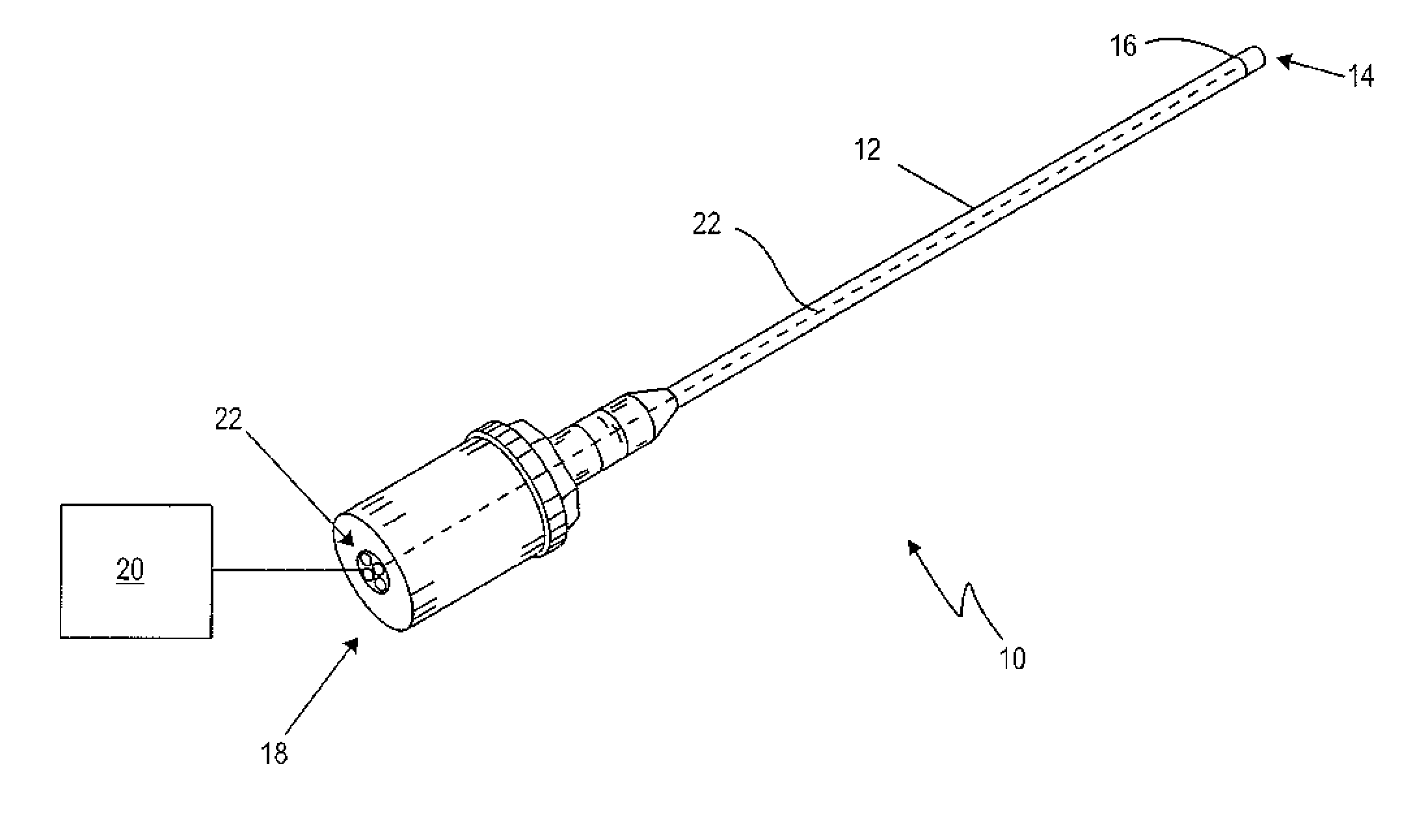
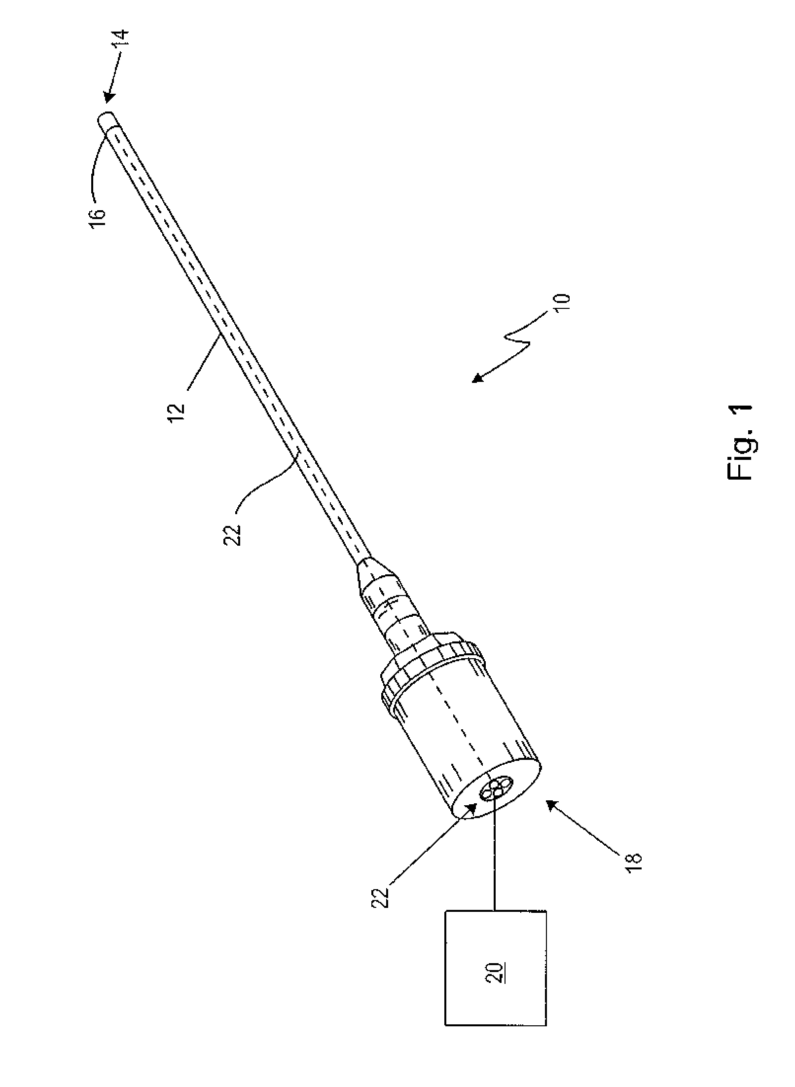
[0073]FIG. 1 shows a preferred embodiment of an endoscopic instrument 10. The endoscopic instrument 10, which is embodied as an endoscope, comprises a shaft 12, which has a distal end 14 at which an optical sensor 16 is arranged, and a proximal end 18 for connection to a supply unit 20. Between the optical sensor 16 and the proximal end 18 a data transmission element is arranged. The data transmission element is configured to transmit at least two signals differentially. The data transmission element is configured as a star quad cable 22. In a further embodiment (not shown), the star quad cable 22 continues over the proximal end 18 to the supply unit 20. Further, an optical unit (not shown) may be associated with the optical sensor 16, the optical unit being provided distally, i.e. in the optical path, before the optical sensor 16. Therefore, the optical sensor 16 may or may not be arranged at the very distal end of the endoscopic instrument 10.

[0074]FIG. 2 shows a schematic cross s...


PUM


Abstract

There is disclosed an endoscopic instrument comprising a shaft having a distal end at which at least one optical sensor is arranged and a proximal end configured for a connection to a supply unit, further comprising a data transmission element which is provided between the at least one optical sensor and the proximal end and which is configured to differentially transmit at least two signals. The data transmission element is embodied as a star quad cable.

Description

CROSS REFERENCES TO RELATED APPLICATIONS[0001]This application claims priority from German patent application DE 10 2010 027 400.3, filed on Jul. 15, 2010. The entire contents of this priority application is incorporated herein by reference.BACKGROUND OF THE INVENTION[0002]Endoscopic optical and optoelectronic sensors comprise CCD (Charge-Coupled Device)—or CMOS (Complementary Metal Oxide Semiconductor)—modules. The requirements regarding the restricted dimensions of endoscopic instruments can make it difficult to provide the image data processing units and control units for these sensors at the distal end of the endoscopic instrument. Therefore, data transmission elements are provided which transmit the image data from the optical sensors to a supply unit and vice versa transmit control signals and driving clock cycles from the supply unit to the optical sensor.[0003]For the data transmission of analog video signals and driver clocks having a relatively high frequency, coaxial cond...

Claims


Application Information

Patent Timeline
Patent Type & Authority Applications(United States)
IPC IPC(8): A61B1/06A61B1/07
CPCA61B1/00114A61B1/00193H04N2005/2255H01B11/005H04N5/23203A61B1/05H04N23/555H04N23/66
Inventor BAUM, ECKARTSCHWARZ, PETER
Owner KARL STORZ GMBH & CO KG
Learn More