
Syringe with Co-Molded Hub and Cannula

a hub and cannula technology, which is applied in the field of hubs of syringes, can solve the problems of prolonged exposure of medication to adhesive, increased patient perception, and undesirable adhesive bonding of cannulas to the barrel of syringes

Active Publication Date: 2012-01-12
WEST PHARM SERVICES INC
View PDF3 Cites 29 Cited by
  • Summary
  • Abstract
  • Description
  • Claims
  • Application Information

AI Technical Summary

Benefits of technology

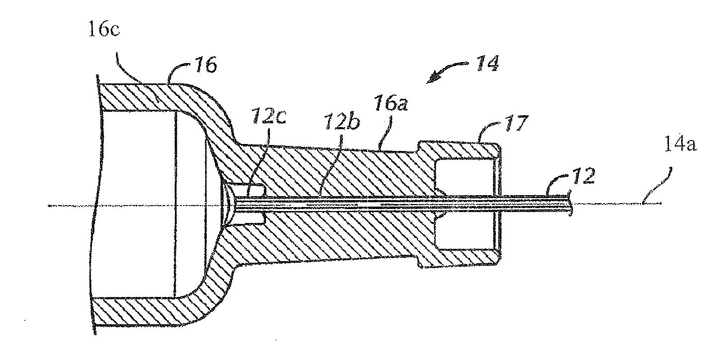
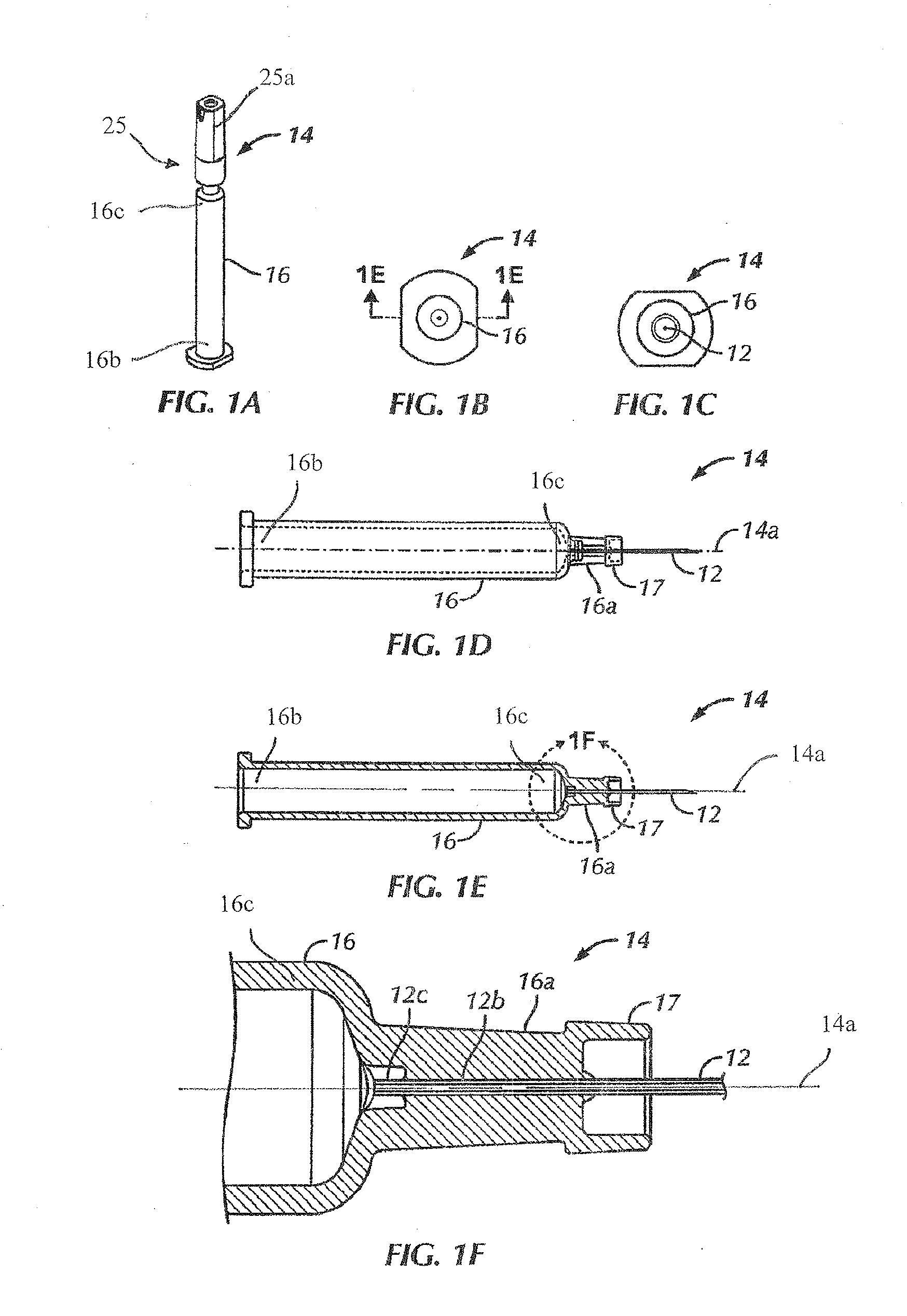
The present patent application is about a prefilled syringe for injecting medicament into a patient. The syringe has a barrel made of polymeric material, a cannula, and a hub. The hub has a rib section and a cap. The rib section has a cruciform cross-section and the cap has a U-shaped cross-section. The cannula is positioned coaxially with the longitudinal axis of the barrel and is fixed to the distal end of the barrel. The technical effect of this design is that it provides a syringe that is easy to use and can be safely injected into a patient.

Problems solved by technology

Bends or buns in the cannula resulting from the manufacturing process can increase perceived pain of the patient.
Adhesive bonding to affix a cannula to the barrel of the syringe may be undesirable in certain situations because the adhesive may contain chemicals that could leach into the medication in the syringe.
The medication may be prefilled in to the syringe, resulting in potentially prolonged exposure of the medication to the adhesive.
The leaching chemicals of the adhesive may have an adverse impact on the medication / biological compound(s) maintained in the barrel of the syringe, such as altering the efficacy and / or stability of the syringe contents that eventually enter the patient.
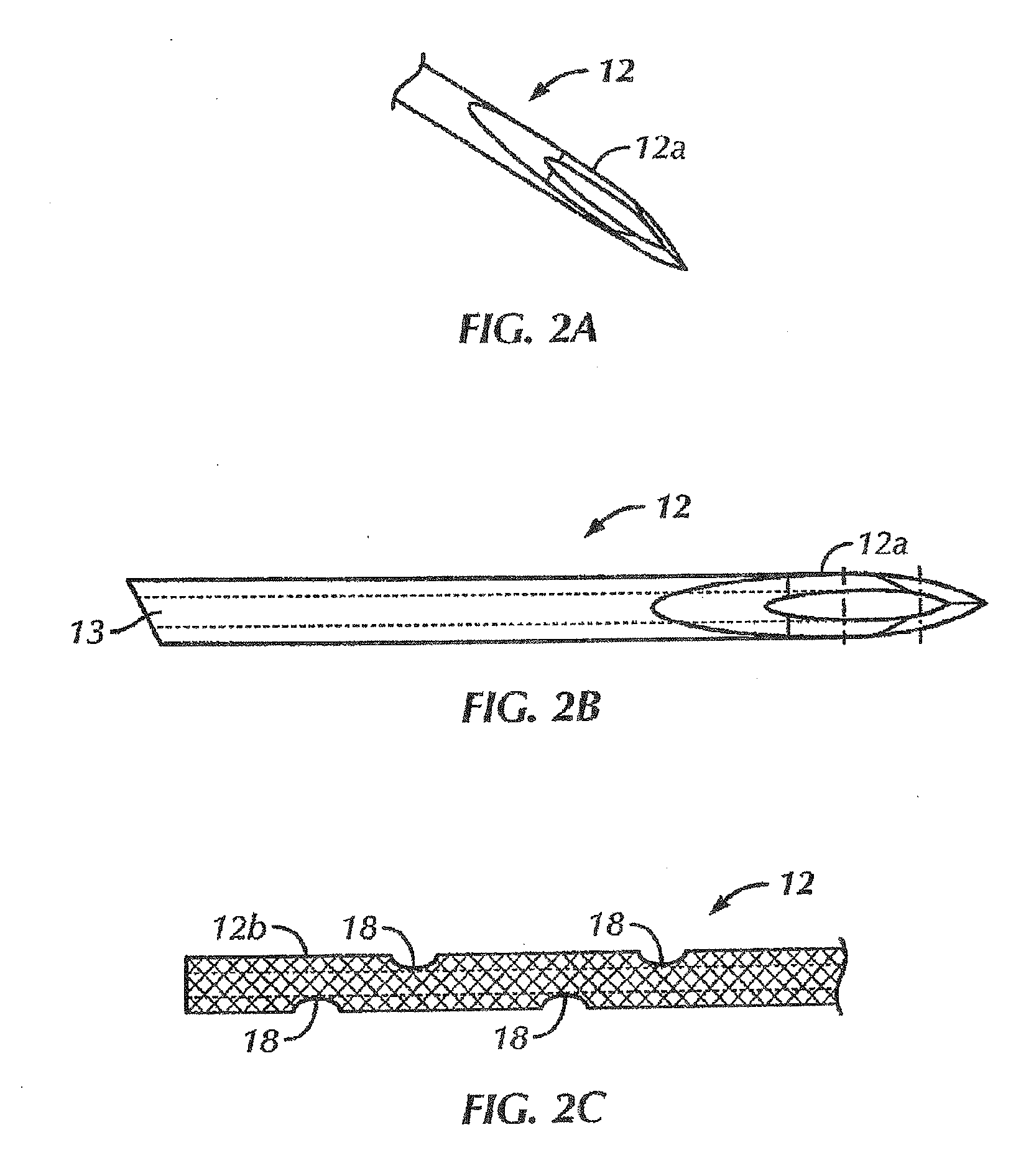
Regardless of the attachment method, it is difficult to position, hold, and / or mount a fragile, fine gauge cannula without damaging the cannula.

Method used


Image

  • Syringe with Co-Molded Hub and Cannula
  • Syringe with Co-Molded Hub and Cannula
  • Syringe with Co-Molded Hub and Cannula

Examples


Embodiment Construction

[0037]Certain terminology is used in the following description for convenience only and is not limiting. The words “right”, “left”, “lower” and “upper” designate directions in the drawings to which reference is made. The words “inwardly” or “distally” and “outwardly” or “proximally” refer to directions toward and away from, respectively, the geometric center or orientation of the syringe and related parts thereof Unless specifically set forth herein, the terms “a”, “an” and “the” are not limited to one element but instead should be read as meaning “at least one”. The terminology includes the words noted above, derivatives thereof and words of similar import.

[0038]Referring to the drawings, wherein like numerals indicate like elements throughout, there is shown in FIGS. 3-7 and 11-13 a first preferred embodiment of a collet mechanism 10. The collet mechanism 10 is used to position and hold a cannula 12 in place during insert molding of a staked needle or syringe, generally 14, withou...


PUM

PropertyMeasurementUnit
temperatureaaaaaaaaaa
radii r1aaaaaaaaaa

Abstract

A prefilled syringe for injecting medicament into a patient includes a barrel constructed of a polymeric material, a cannula and a hub. The barrel has a diameter, a longitudinal axis, a proximal end and a distal end. The cannula has a proximal end and a tip opposite the proximal end. The proximal end of the cannula is fixed to the distal end of the barrel. The cannula is positioned generally coaxially with the longitudinal axis. The hub is integrally formed with the distal end. The hub includes a rib section and a cap. The rib section has a generally cruciform cross-section taken along a rib plane. The rib plane is generally perpendicular to the longitudinal axis. The cap has a generally U-shaped cross-section taken along a longitudinal plane. The longitudinal plane is generally parallel to the longitudinal axis.

Description

CROSS-REFERENCE TO RELATED APPLICATIONS[0001]This application is a continuation-in-part application of U.S. patent application Ser. No. 12 / 680,609, filed Mar. 29, 2010, which is a Section 371 of International Application No. PCT / US09 / 031112, filed Jan. 15, 2009, which was published in the English language on Jul. 23, 2009 under International Publication No. WO 2009 / 091895 A2 and claims priority to U.S. Provisional Patent Application No. 61 / 021,186, filed Jan. 15, 2008, the disclosures of which are incorporated herein by reference in their entirety.BACKGROUND OF THE INVENTION[0002]The present invention relates to a hub for a syringe that is co-molded with a cannula and a method for forming or co-molding the cannula to the syringe barrel. The cannula is preferably a fine gauge cannula, which is co-molded to the syringe barrel to form a staked needle device.[0003]The process of bonding a cannula to a syringe barrel involves precisely positioning and then bonding the cannula to the syri...

Claims


Application Information

Patent Timeline
Patent Type & Authority Applications(United States)
IPC IPC(8): A61M5/31A61M5/32
CPCA61M5/3202A61M5/3286A61M5/3293A61M5/343B29L2031/7544B29C45/14065B29C45/14311B29C45/14426B29C2045/14139A61M2005/3109
Inventor LUNDQUIST, JON TYLER
Owner WEST PHARM SERVICES INC
Learn More