Wireless IC device component and wireless IC device
- Summary
- Abstract
- Description
- Claims
- Application Information
AI Technical Summary
Benefits of technology
Problems solved by technology
Method used
Image
Examples
first preferred embodiment
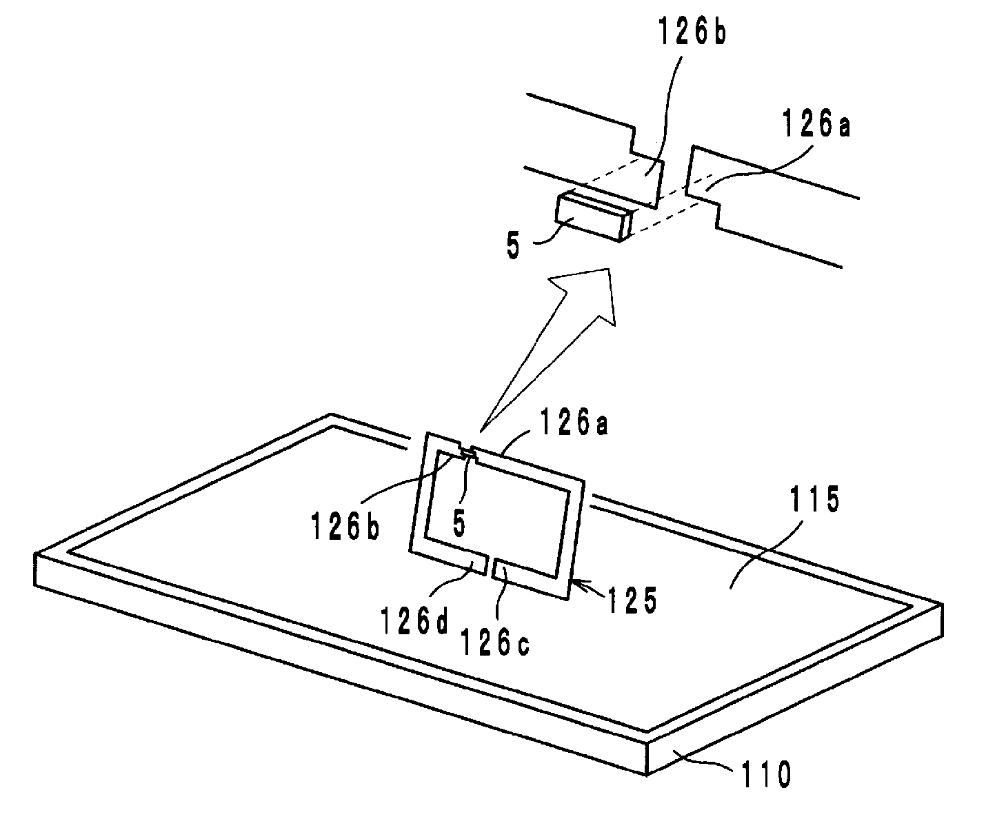
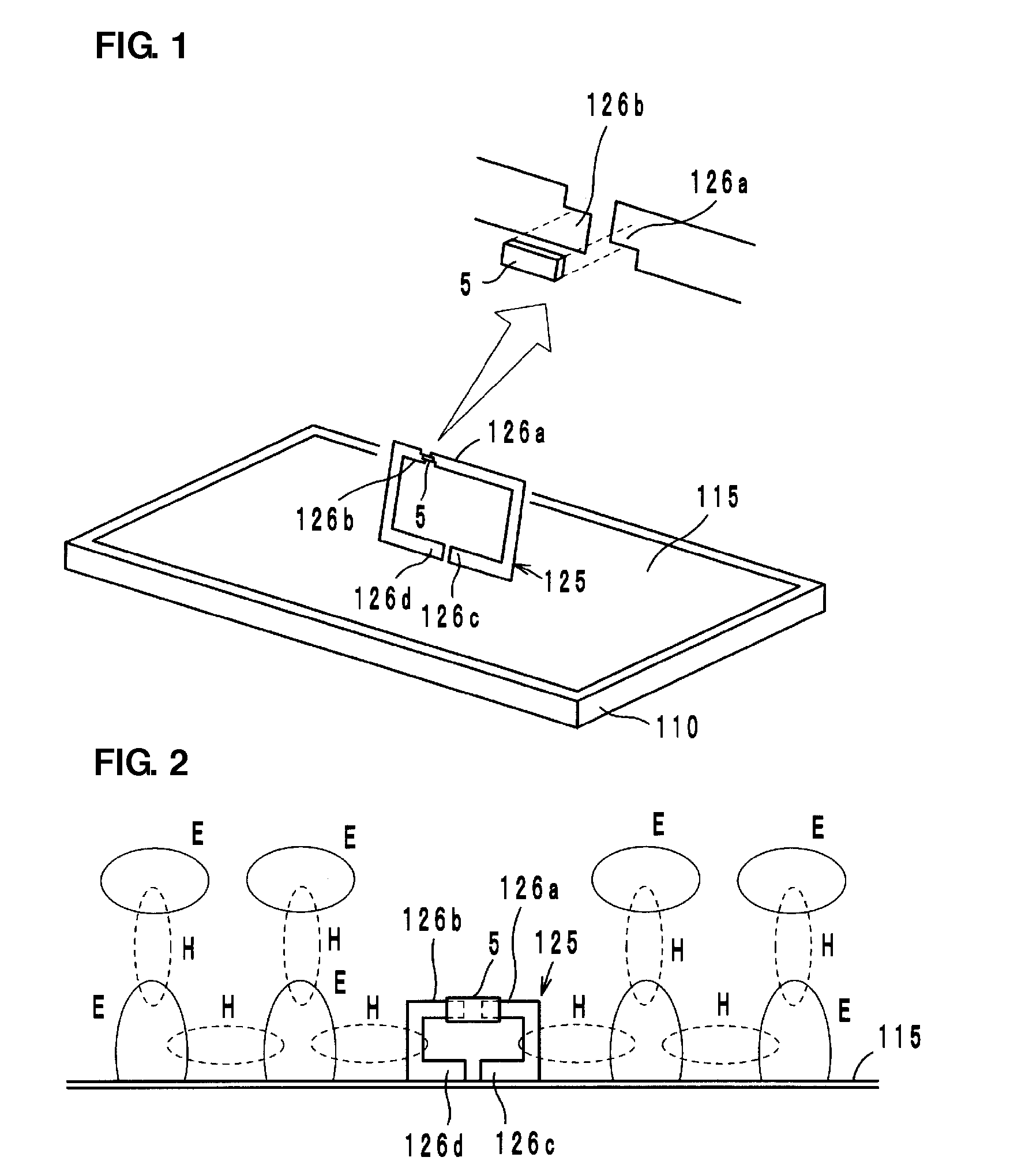
[0039]A wireless IC device according to a first preferred embodiment of the present invention preferably includes a wireless IC chip 5 arranged to process transmission and reception signals having certain frequencies, a radiation plate 115 provided on a base 110, such as a polyethylene terephthalate (PET) film, for example, and a coupling electrode 125 provided on a base (not shown), such as a PET film, for example, as shown in FIG. 1.
[0040]The coupling electrode 125 preferably includes a pair of coupling portions 126a and 126b to be coupled to the wireless IC chip 5 and a pair of opposing ends 126c and 126d defined by a cutout of the coupling electrode 125. The wireless IC chip 5 preferably includes, for example, a clock circuit, a logic circuit, and a memory circuit. Necessary information is stored in the wireless IC chip 5. A pair of input-output terminal electrodes (not shown) is provided on the rear surface of the wireless IC chip 5. The pair of input-output terminal electrodes...
second preferred embodiment
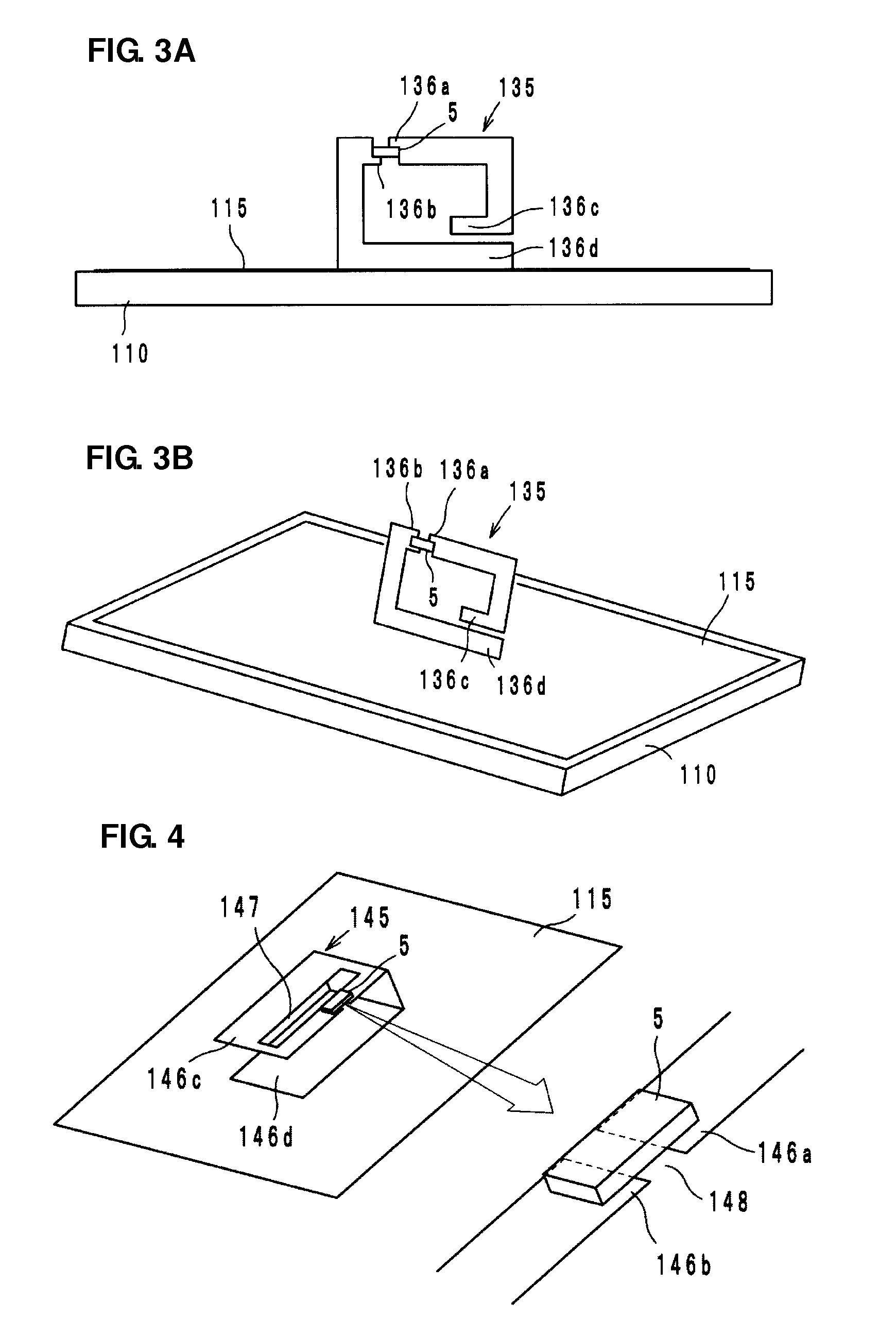
[0052]A wireless IC device component according to a second preferred embodiment of the present invention preferably includes a coupling electrode 135, as shown in FIGS. 3A and 3B. The coupling electrode 135 preferably includes a pair of coupling portions 136a and 136b arranged to be coupled to the wireless IC chip 5 and a pair of opposing ends 136c and 136d. The opposing ends 136c and 136d are capacitively coupled to each other.
[0053]The opposing end 136c is capacitively coupled to the opposing end 136d, so that the coupling electrode 135 electrically forms an annular electrode and functions as a magnetic-field antenna. The wireless IC device component functions as a wireless IC device with the coupling electrode 135 being coupled to the radiation plate 115, similarly to the coupling electrode 125 shown in the first preferred embodiment.
[0054]The coupling electrode 135 has an inductive reactance (XL: jωL) caused by the electrical length and a capacitive reactance (XC: 1 / jωC) caused ...
third preferred embodiment
[0056]A wireless IC device component according to a third preferred embodiment of the present invention preferably includes a coupling electrode 145 having a U-shape in a side view, as shown in FIG. 4. The coupling electrode 145 is preferably provided from the front surface of a base (not shown) made of resin, for example, to the rear surface thereof and includes an opening 147 and a slit 148 extending to the opening 147 on its surface. The opening 147 and the slit 148 define a pair of coupling portions 146a and 146b to be coupled to the wireless IC chip 5. The coupling electrode 145 includes opposing ends 146c and 146d. The opposing ends 146c and 146d are capacitively coupled to each other.
[0057]The opposing end 146c is capacitively coupled to the opposing end 146d, so that the coupling electrode 145 electrically forms an annular electrode, functions as a magnetic-field antenna, and is coupled to the radiation plate 115. The operational effects of the third preferred embodiment are...
PUM
 Abstract
Description
Claims
Application Information
 - R&D
- Intellectual Property
- Life Sciences
- Materials
- Tech Scout
- Unparalleled Data Quality
- Higher Quality Content
- 60% Fewer Hallucinations
Browse by: Latest US Patents, China's latest patents, Technical Efficacy Thesaurus, Application Domain, Technology Topic, Popular Technical Reports.
© 2025 PatSnap. All rights reserved.Legal|Privacy policy|Modern Slavery Act Transparency Statement|Sitemap|About US| Contact US: help@patsnap.com


