Apparatus and method for switching frequency band of antenna

Inactive Publication Date: 2008-09-18
ADVANCED CONNECTEK INC
View PDF7 Cites 8 Cited by
  • Summary
  • Abstract
  • Description
  • Claims
  • Application Information

AI Technical Summary

Benefits of technology

[0024]The antenna, switching device, driving device, radio frequency module, and system circuit module included in the apparatus for switching the frequency band of the antenna are all able to be integrated into a main body through an integrated circuit process, so as to form a single antenna system without increasing the volume of the antenna. The present invention adjusts a frequency width of an antenna to be corresponding to one of a plurality of communication systems or communication channels, such that when various users use different communication systems or different communication channels to communicate, the antenna can be switched to a corresponding frequency band to cover the one required by the communication system or communication channel, such that the applicable frequency band of the antenna can be effectively increased.

Problems solved by technology

However, if no communication channel is available during a busy period, it will sequentially result in a significant problem that the communication device cannot work.

Method used


Image

  • Apparatus and method for switching frequency band of antenna
  • Apparatus and method for switching frequency band of antenna
  • Apparatus and method for switching frequency band of antenna

Examples


Embodiment Construction

[0035]Reference will now be made in detail to the present preferred embodiments of the invention, examples of which are illustrated in the accompanying drawings. Wherever possible, the same reference numbers are used in the drawings and the description to refer to the same or like parts.

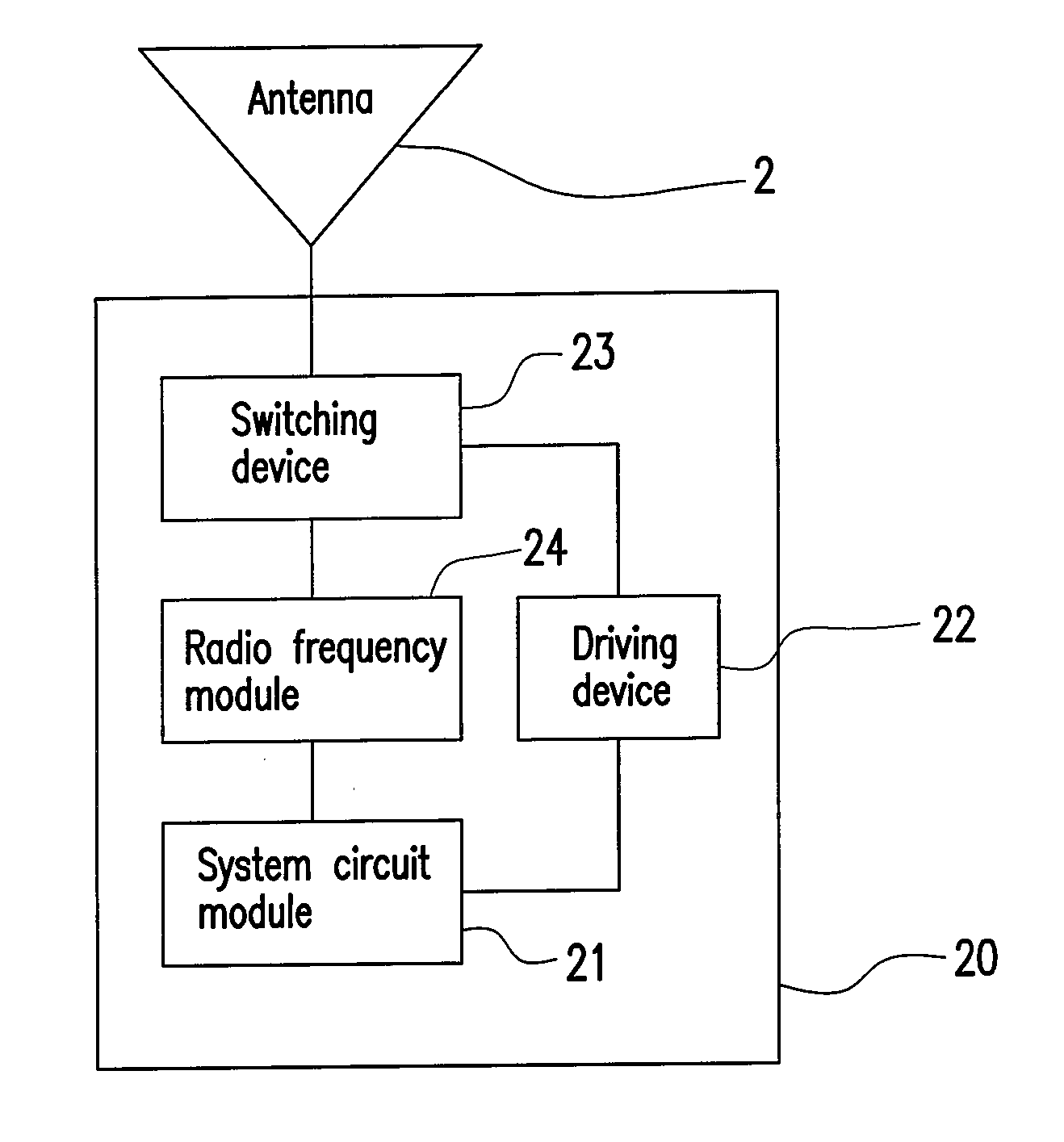
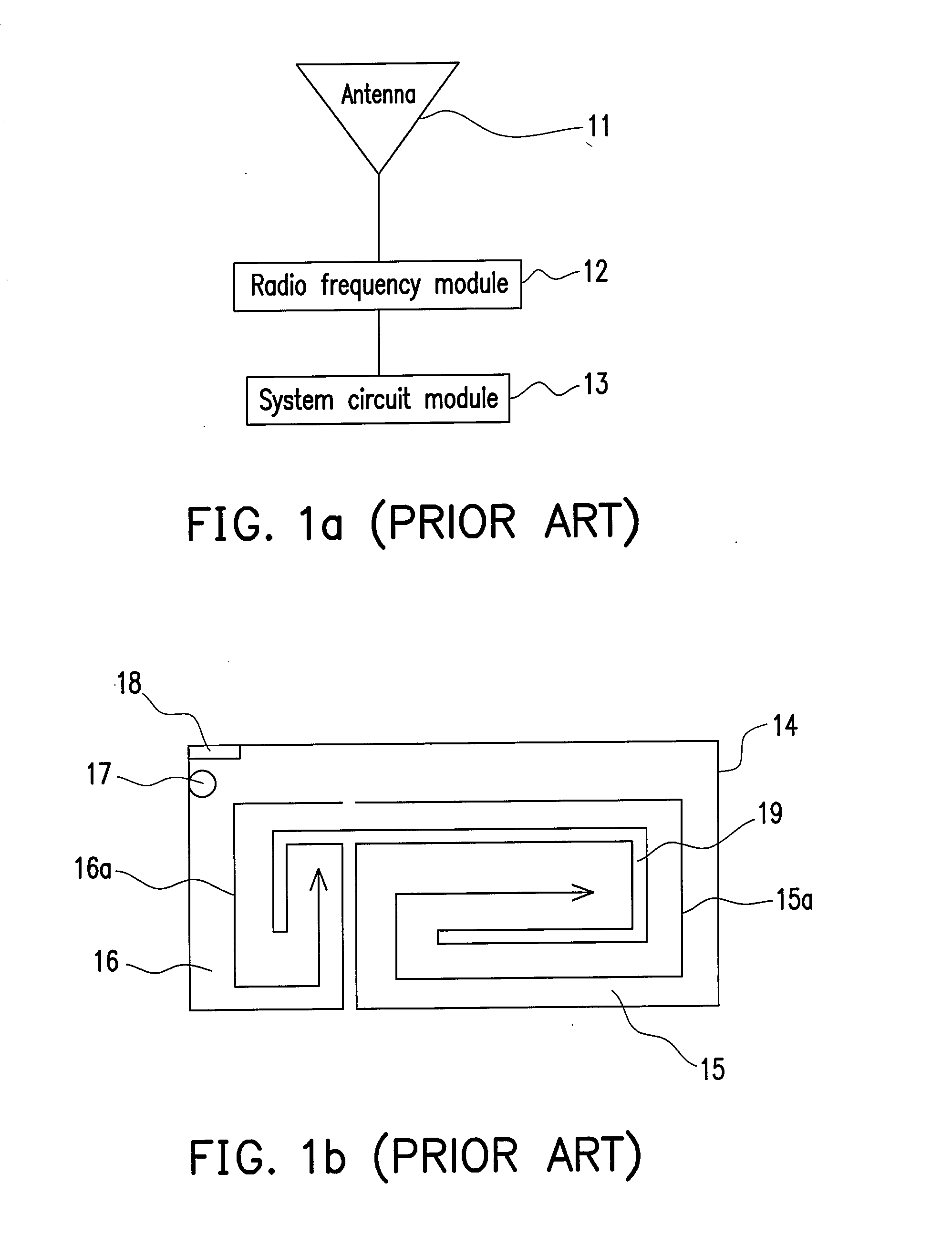
[0036]FIG. 2a is a block diagram illustrating an apparatus for switching a frequency band of an antenna according to an embodiment of the present invention. Referring to FIG. 2a, the apparatus 20 is disposed in an electronic device such as a mobile phone, a notebook, or a digital TV, and primarily includes a system circuit module 21, a switching device 22, a driving device 23, and a radio frequency module 24. The apparatus 20 is coupled to an antenna 2 for switching the frequency band thereof, where the antenna 2 is an antenna adopted by a general wireless communication device for receiving and transmitting signals, and the structure thereof is similar to that of the conventional antenna as shown in ...


PUM


Abstract

An apparatus and a method for switching a frequency band of an antenna, used in an electronic device having an antenna are provided. The apparatus comprises a driving device, a switching device, and a radio frequency module. The switching device is used for adjusting the frequency band of the antenna to cover a system frequency band of a communication system adopted by the electronic device. The driving device is used for receiving a switching command from the electronic device and driving the switching device accordingly, in which the switching command indicates the communication system adopted by the electronic device. The radio frequency module is used for performing down frequency conversion on the signals output by the switching device and performing up frequency conversion on the signals to be input to the switching device. Accordingly, more than two frequency bands can be supported by the electronic device with a single antenna.

Description

CROSS-REFERENCE TO RELATED APPLICATION[0001]This application claims the priority benefit of Taiwan application serial no. 96109116, filed on Mar. 16, 2007. The entirety the above-mentioned patent application is hereby incorporated by reference herein and made a part of specification.BACKGROUND OF THE INVENTION[0002]1. Field of the Invention[0003]The present invention generally relates to an apparatus and a method for switching a frequency band of an antenna, and in particular, to an apparatus and a method applicable to switching a frequency band of an antenna so as to increase the range of the frequency band supported by a wireless communication system.[0004]2. Description of Related Art[0005]FIG. 1a is a block diagram illustrating a conventional wireless communication system. Referring to FIG. 1a, the wireless communication system includes an antenna 11, a radio frequency module 12, and a system circuit module 13. The antenna 11 is, for example, an antenna used in a general wireles...

Claims


Application Information

Patent Timeline
IPC IPC(8): H04B1/40
CPCH01Q9/145H04B1/0458H04B1/0053
Inventor HSIAO, CHIH-RENLIAO, PO-YUANCHIU, TSUNG-WENHSIAO, FU-REN
Owner ADVANCED CONNECTEK INC
Why Eureka
Try Eureka