Eureka AIR delivers breakthrough ideas for toughest innovation challenges, trusted by R&D personnel around the world.

Antenna element, antenna module, and communication device

Pending Publication Date: 2021-06-03
MURATA MFG CO LTD
View PDF0 Cites 1 Cited by
  • Summary
  • Abstract
  • Description
  • Claims
  • Application Information

AI Technical Summary

Benefits of technology

The present patent is aimed at improving the radiation characteristics of an antenna element. It proposes a solution for an antenna element with a radiation electrode and a ground electrode arranged opposite each other. The invention proposes a design that improves the radiation characteristics of a specific part of the radiation electrode that is opposite to the first ground electrode without being opposite to the second ground electrode.

Problems solved by technology

In some cases, however, depending on the space where the antenna element is arranged, portions that can be formed thick may be limited in the dielectric substrate.
In such cases, the radiation electrode and the ground electrode need to be arranged so as to lie opposite to each other in a thin portion in the dielectric substrate, and it may thus be impossible to ensure a distance between the radiation electrode and the ground electrode.
As a result, it may be difficult to improve the radiation characteristics of the antenna element.

Method used


Image

  • Antenna element, antenna module, and communication device
  • Antenna element, antenna module, and communication device
  • Antenna element, antenna module, and communication device

Examples


first embodiment

Second Variation of First Embodiment

[0051]In each of the first embodiment and the first variation thereof, the antenna element that includes one radiation electrode is described. The number of radiation electrodes may be two or more. In a second variation of the first embodiment, an antenna element that includes two radiation electrodes is described.

[0052]FIG. 5 illustrates an antenna module 1100B including an antenna element 100B according to the second variation of the first embodiment, which is viewed as a plane in the X axis direction. In the configuration of the antenna module 1100B, the antenna element 100 in FIG. 2 is replaced with the antenna element 100B. In the configuration of the antenna element 100B in FIG. 5, a radiation electrode 112 and a via conductor 152 are added to the antenna element 100 in FIG. 2. Since the configuration other than these is similar, the descriptions thereon are not repeated.

[0053]As illustrated in FIG. 5, the radiation electrode 112 is arranged...

second embodiment

Second Variation of Second Embodiment

[0093]In each of the second embodiment and the first variation thereof, the case where the dielectric substrate of the antenna element includes one bent portion is described. The dielectric substrate may include a plurality of bent portions. In a second variation of the second embodiment, the dielectric substrate includes two bent portions is described.

[0094]FIG. 11 illustrates an antenna module 1200B according to the second variation of the second embodiment, which is viewed as a plane in the X axis direction. In the configuration of the antenna module 1200B, the antenna element 200 of the antenna module 1200 in FIG. 9 is replaced with an antenna element 200B. In the configuration of the antenna element 200B, the dielectric substrate 220 is replaced with a dielectric substrate 220B while radiation electrodes 202B, 205B, 208B, and 211B, radiation electrodes 203B, 206B, 209B, and 212B, ground electrodes 232B and 281B to 284B, via conductors 252B, ...

third embodiment

Second Variation of Third Embodiment

[0116]In each of the third embodiment and the first variation thereof, the configuration where a dielectric layer that is included in the plurality of dielectric layers making up the antenna element and is formed from a flexible material includes one bent portion is described. Described in a second variation of the third embodiment is a configuration where the dielectric layer includes two bent portions and bends so as to be wound around an end portion of the mounting board.

[0117]FIG. 14 illustrates a communication device 3000B according to the second variation of the third embodiment, which is viewed as a plane in the X axis direction. In the configuration of the communication device 3000B, the antenna module 1300 of the communication device 3000 in FIG. 12 is replaced with an antenna module 1300B. In the configuration of the antenna module 1300B, the antenna element 200 and the RFIC 240 of the antenna module 1300 are replaced with an antenna ele...


PUM


Abstract

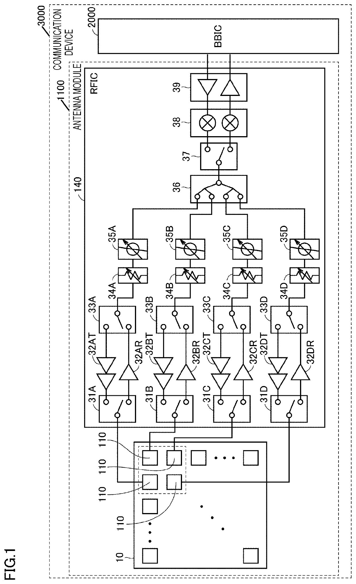
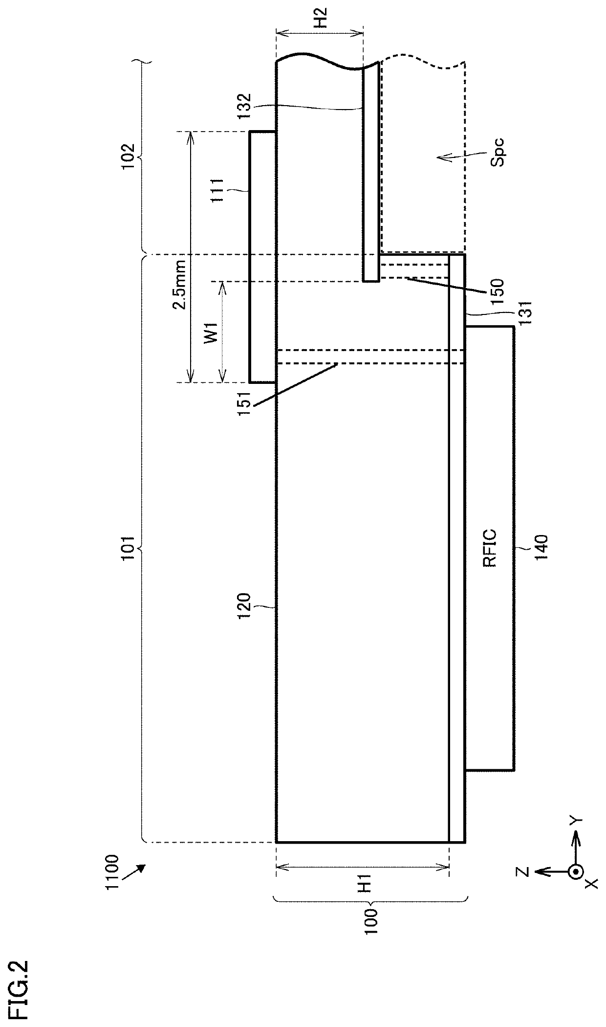
An antenna element includes a dielectric substrate, a first ground electrode, a second ground electrode, a via conductor, and a radiation electrode. The dielectric substrate includes a first portion shaped like a flat plate and a second portion thinner than the first portion. The first ground electrode is arranged in the first portion. The second ground electrode is arranged in the second portion. The via conductor couples the first ground electrode and the second ground electrode. A distance between the radiation electrode and the first ground electrode in a first thickness direction is more than a distance between the radiation electrode and the second ground electrode in a second thickness direction. Part of the radiation electrode lies opposite to the first ground electrode without lying opposite to the second ground electrode.

Description

CROSS REFERENCE TO RELATED APPLICATION[0001]This is a continuation of International Application No. PCT / JP2019 / 030419 filed on Aug. 2, 2019 which claims priority from Japanese Patent Application No. 2018-150512 filed on Aug. 9, 2018. The contents of these applications are incorporated herein by reference in their entireties.BACKGROUND OF THE DISCLOSUREField of the Disclosure[0002]The present disclosure relates to an antenna element, where a radiation electrode and a ground electrode are arranged so as to lie opposite to each other, an antenna module including the antenna element, and a communication device including the antenna module.Description of the Related Art[0003]An antenna element where a radiation electrode and a ground electrode are arranged so as to lie opposite to each other has been known to date. For example, International Publication No. 2012 / 081288 (Patent Document 1) discloses a radio frequency package including an antenna where a radiation electrode and a ground co...

Claims


Application Information

Patent Timeline
IPC IPC(8): H01Q9/04H01Q1/38H01Q11/14
CPCH01Q9/0407H01Q11/14H01Q1/38H01Q1/243H01Q1/2283H01Q21/065H01Q21/08H01Q3/26
Inventor SUDO, KAORUMORI, HIROTSUGUONAKA, KENGO
Owner MURATA MFG CO LTD
Why Eureka
Eureka Blog
Learn More