Method and apparatus for oiling rotating or oscillating components

a technology of rotating or oscillating components and heating methods, which is applied in the direction of engine components, lubrication temperature control, pressure lubrication with lubrication pump, etc., can solve the problem of small reduction in fuel consumption, major exhaust emissions, and inconvenient routing of oil bypass lines for raising the temperature more quickly, so as to increase the heating effect

Inactive Publication Date: 2012-01-12
INO8
View PDF8 Cites 16 Cited by
  • Summary
  • Abstract
  • Description
  • Claims
  • Application Information

AI Technical Summary

Benefits of technology

[0031]The sealing of the valves in the exhaust gas line is of particular importance, since a tight seal not only increases the heating effectiveness but also prevents, in the closed position, that the oil is heated up unintentionally, for example at high engine loads and high numbers of rotation (rpm). This makes the application of an additional oil cooler redundant. According to the invention it is thus advantageous if the valves in the exhaust gas line are designed as a single-piece three-way valve and that said valves take the form of double-sided acting poppet valves, wherein the poppet has two sealing surfaces. One of the sealing surfaces is disposed at the outer end of the valve, like on an exhaust valve in the cylinder head of a combustion engine. The second sealing surface is disposed on the opposite side of the poppet, the side from which the valve stem extends to the actuating device. In its activated state, the outer end of the valve shuts off the exhaust bypass, and in the deactivated state, the inner sealing surface of the poppet shuts off the line to the heat exchanger.

Problems solved by technology

Furthermore, the majority of the exhaust emissions occur during the cold start phase of the combustion engine when the catalytic converter has not yet reached the required operating temperature.
On the other hand, this poses the problem of how to protect the engine, and in particular the engine oil, from overheating in this heating process.
The known solutions are very elaborate and result only in a small reduction in the fuel consumption, hence a practical implementation hardly ever takes place for economic reasons.
The routing chosen for the oil bypass line is not advantageous for raising the temperature more quickly.
This makes the application of an additional oil cooler redundant.

Method used


Image

  • Method and apparatus for oiling rotating or oscillating components
  • Method and apparatus for oiling rotating or oscillating components
  • Method and apparatus for oiling rotating or oscillating components

Examples


Embodiment Construction

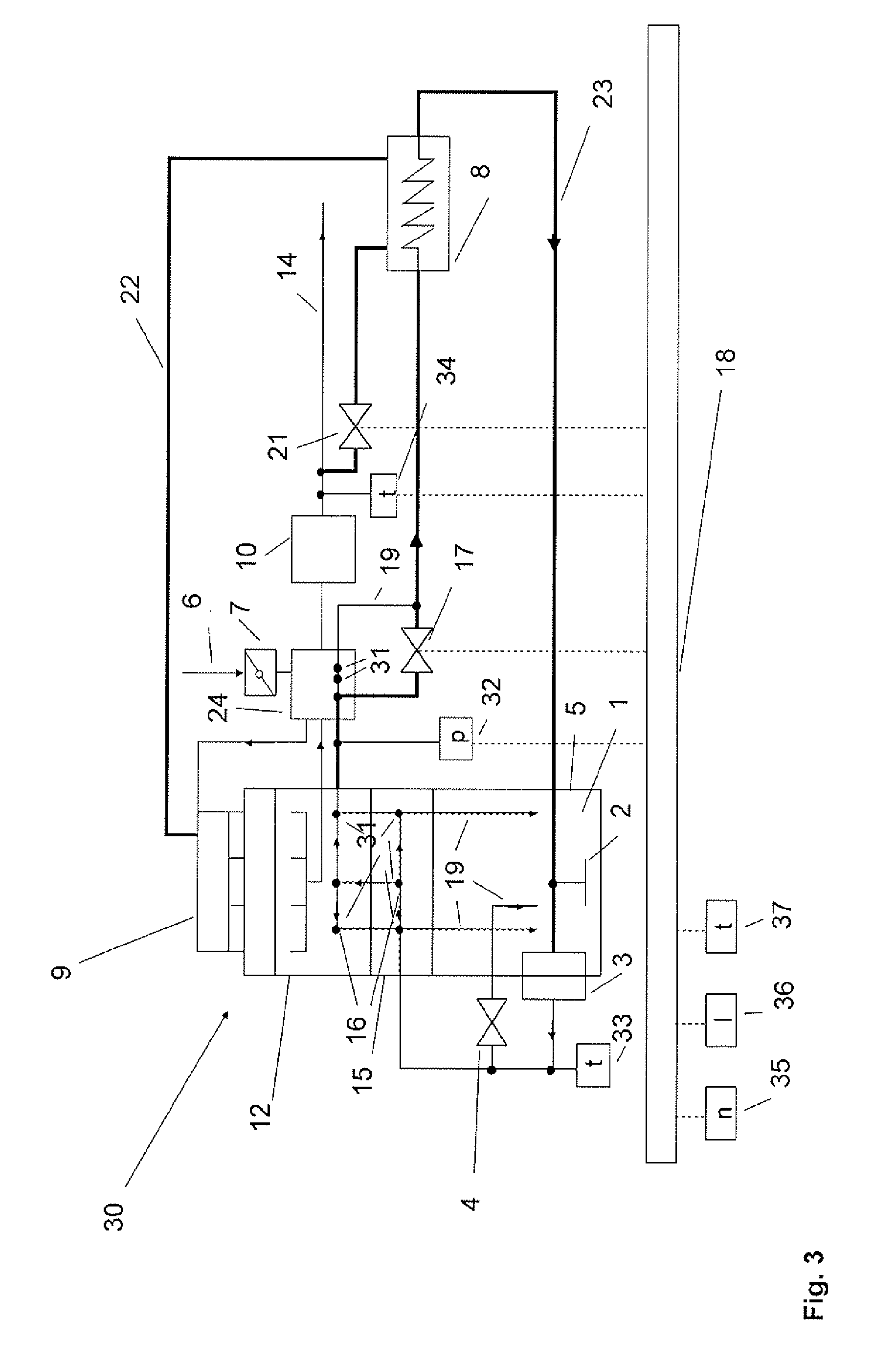
[0040]FIG. 1 depicts a combustion engine 30 in a schematic representation. The combustion engine 30 comprises an exhaust line 14 in which a catalytic converter 10 is disposed. In the exemplary embodiment shown the combustion engine 30 is depicted as a four-cylinder engine whose four cylinder manifolds merge into a common exhaust gas line 14.

[0041]Seen in the exhaust gas flow direction of the exhaust gas, a heat exchanger 8 is disposed in the exhaust gas line 14 downstream of the catalytic converter 10, and a turbocharger 24 is disposed upstream of the catalytic converter. The combustion engine 30 comprises a lubricating oil system 16. The lubricating oil system comprises an oil sump 1, an oil suction tube 2, an oil pump 3, devices 31 to be lubricated of a cylinder head 12 and of a cylinder block 15 and of a turbocharger 24, oil pan 5, as well as an oil relief pressure valve 4.

[0042]Moreover, a bypass valve 17 is assigned to the lubricating oil system 16. The bypass valve 17 regulate...


PUM


Abstract

A method is provided for heating a lubricating system. At low temperatures, lubricating oil has a high viscosity which requires more energy to be overcome than at higher temperatures. The method speeds up the heating behavior and thereby reduces the energy requirement of lubricating systems. The method can be used to heat lubricating systems for combustion engines or transmissions, preferably automatic transmissions, including at least one oil suction tube which is disposed in an oil sump and an oil bypass line bypassing the oil return lines. A bypass valve is disposed in the oil bypass line. The oil bypass line and/or at least one of the oil return lines is connected to the suction line of an oil pump and the pressure line of a lubricating system and, during use, runs in a combustion engine, preferably through at least one cylinder head, a cylinder block, or a turbocharger, and during use in a transmission it preferably runs through at least one heat exchanger of the combustion engine and/or through at least one electrical heating element. When a defined limit temperature is no longer met and a defined minimum pressure of the lubricating oil in the pressure line of the lubricating system is exceeded, the bypass valve is opened at least partially, so that a partial flow of the lubricating oil does not flow through the oil sump during the warm-up phase of the lubricating system. The lubricating oil flowing through the oil bypass line and/or at least one of the oil return lines is heated by a heat exchanger. The method is particularly suited for quickly heating combustion engines and transmissions in motor vehicles.

Description

BACKGROUND AND SUMMARY[0001]The invention concerns a method for heating a lubricating system of rotating or oscillating components, in particular for a combustion engine or a transmission, comprising at least one oil suction tube which is disposed inside an oil sump, and a bypass line which bypasses the oil return line, wherein a valve is disposed in the bypass line.[0002]DE 27 53 716 concerns a heating device emitting hot air designed for motor vehicles powered by a combustion engine, comprising a heat exchanger which can be supplied with atmospheric air to transfer heat to a heat transfer medium flowing inside a pipe circuit, said pipe circuit having also a heat exchanger connected therein that absorbs exhaust gas heat from the combustion engine and transfers it to the heat transfer medium. The pipe circuit for the heat exchanger of the heating device is in heat-transferring connection with at least the lubricating oil circuit of the combustion engine. In this instance a heat tran...

Claims


Application Information

Patent Timeline
Patent Type & Authority Applications(United States)
IPC IPC(8): F01M5/00
CPCF01M5/001F01M5/002F01M5/005F01M5/02F01M11/0004F02B2075/027F01M1/02F02B2075/025F01M11/02
Inventor WILL, FRANK
Owner INO8
Why Eureka
Try Eureka