
Knitting system with flattened guide channels

a guide channel and knitting technology, applied in knitting, weft knitting, textiles and papermaking, etc., can solve the problems of difficult hardening of existing strips, wear, and difficulty in hardening, and achieve the effect of easy and precise production, convenient and precise production, and secure guiding

Active Publication Date: 2012-01-12
GROZ BECKERT KG
View PDF14 Cites 5 Cited by
  • Summary
  • Abstract
  • Description
  • Claims
  • Application Information

AI Technical Summary

Benefits of technology

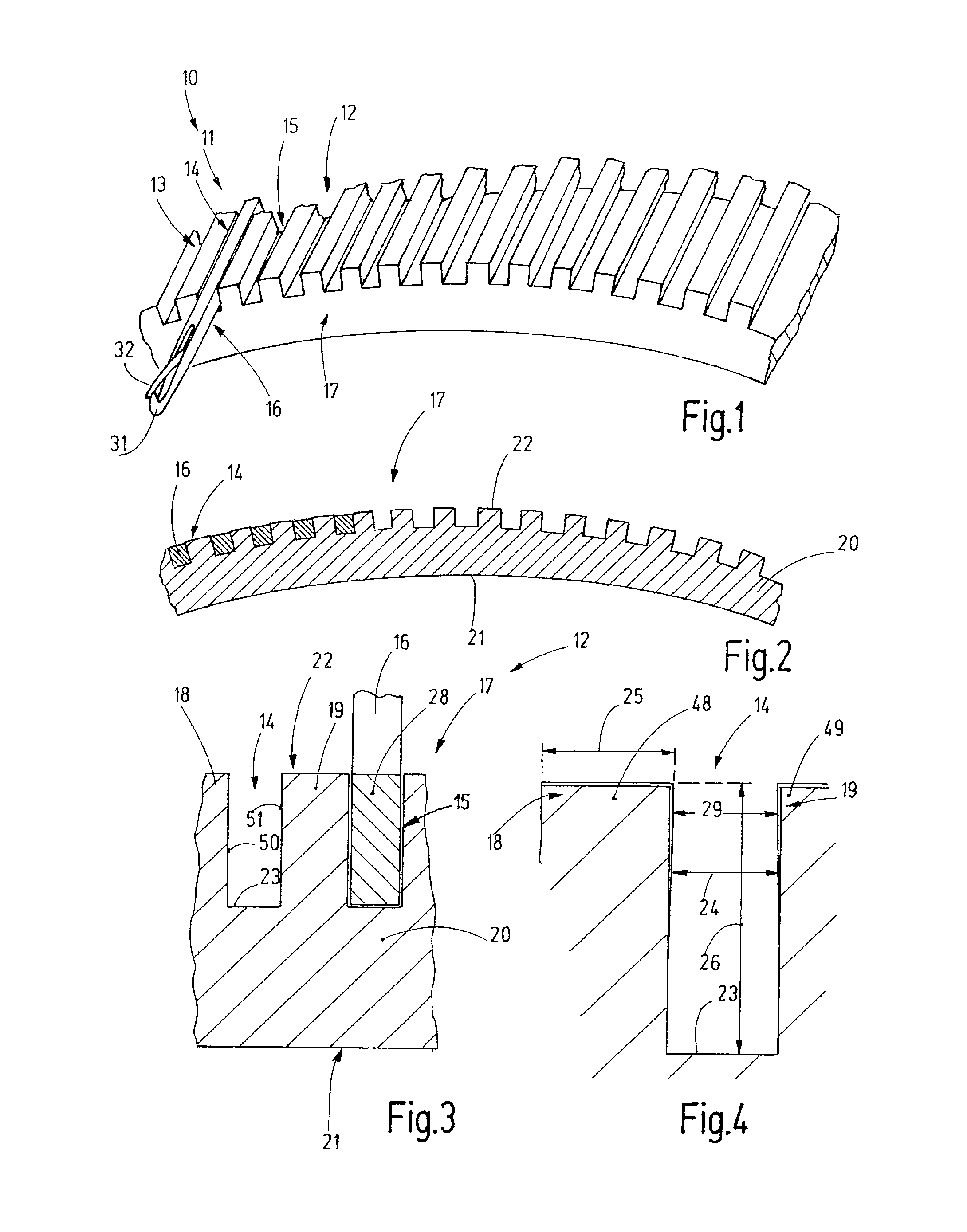
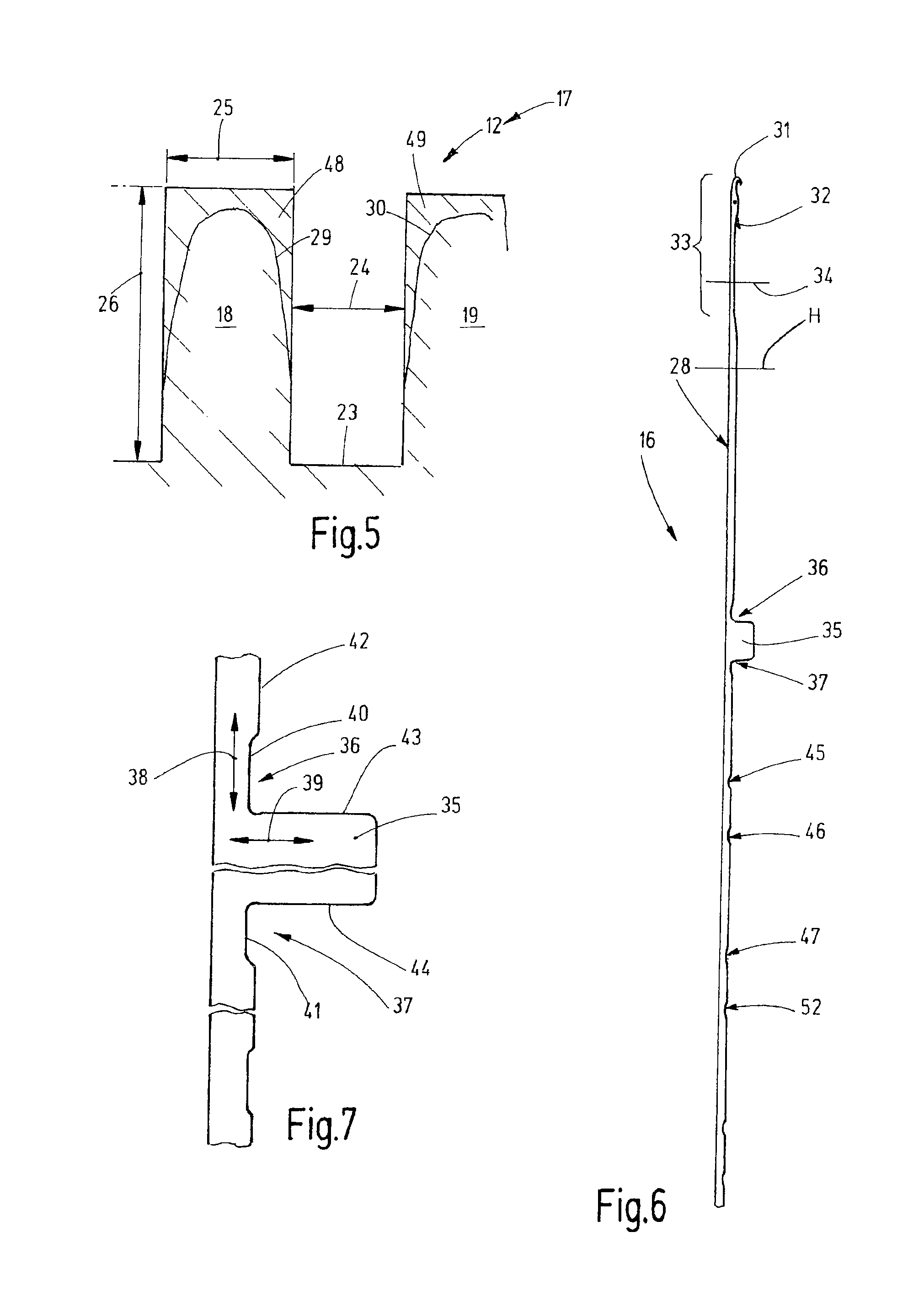
[0014]In a preferred embodiment, the shank cross-section of the knitting tool matches the channel cross-section, in which case the shank cross-section of the knitting tool is minimally smaller, in particular as regards its width, because the knitting tool is movably arranged in the guide channel. The shank cross-section of the knitting tool thus largely matches the channel cross-section. The channel walls do not or not substantially project beyond the shanks of the knitting tools. Due to the shallow channel depth, the resultant knitting cylinder displays a substantially lower weight compared with conventional knitting cylinders. In addition, the weight of the needles moving in the guide channels is almost half of the weight of the prior art needles, this potentially resulting in a savings of weight regarding the knitting device by up to 20%. Inasmuch as the weight saving starts, in particular, on the outside diameter, this results in a substantial reduction of the mass moment of inertia of the knitting cylinder. This is of importance, in particular, for the increase of the working speed of knitting machines, when said knitting machines perform a frequent reversal of rotation during operation, as is the case in reciprocating back-and-forth mode, for example, in the production of patterned goods.
[0022]Preferably, the knitting tool of the novel knitting device comprises a full shank with one or more feet. In the vicinity of the foot, there is at least one recess. Preferably, this recess has the form of an elongated indentation whose length is a multiple of its depth. In this manner, regions are defined between the foot and the shank, said regions displaying a certain elasticity, optionally also a torsional elasticity, and, in any event, reduce the susceptibility of the knitting tool to cracks and breakage.

Problems solved by technology

The idea that has so-far previously been known has met with difficulties in instances of greater degrees of fineness.
However, hardening the existing strips is difficult.
At degrees of fineness greater than 18, hardening is likely to be dispensed with, which, however, can again cause problems of wear.
The design of the strips inserted in the cylinder results in an expensive manufacturing process.
If greater demands are made in view of accuracy, the design using inserted strips on knitting cylinders may lead to difficulties because, in fact, slightly trapezoidal guide channels may result.
If, in contrast, strips are used that themselves are somewhat trapezoidal in form in order to compensate for that, the manufacture is made even significantly more expensive.
Considering this design, there are major problems if the shell-shaped segments attached to the outside of the hollow cylindrical base body are subject to distortion while being hardened.

Method used


Image

  • Knitting system with flattened guide channels
  • Knitting system with flattened guide channels
  • Knitting system with flattened guide channels

Examples


Embodiment Construction

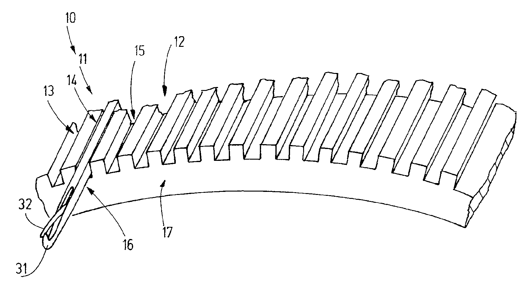
[0036]FIG. 1 shows a knitting device 10 using the example of a circular knitting device 11 comprising a needle bed 12 with a plurality of guide channels 13, 14, 15, etc., as well as knitting tools. In lieu of the knitting tools arranged in each guide channel 13, 14, 15, etc., FIG. 1 shows one needle 16 that is configured, for example, as a latch-type needle.

[0037]In this instance, the needle bed 12 is represented, for example, by a knitting cylinder 17 that has the basic form of a hollow cylinder. Each of FIG. 1 as well as FIG. 2 shows a detail of this knitting cylinder. Preferably, said cylinder consists fully of one piece, i.e., a one-piece component that has no seams and no joints. However, it is also possible, to segment the knitting cylinder 17 or, otherwise, the needle bed 12 (such as, e.g., a dial, a sinker ring or the bed of a flat-bed knitting machine), in which case the individual segments are again disposed to be in one, seamless and jointless piece.

[0038]The seamless and...


PUM


Abstract

A knitting device (10) comprising a needle bed (12) and knitting tools (16), wherein the needle bed (12) is designed so as to be without joints and seams in view of the configuration of its channel walls (18, 19) as well as perpendicularly to the floor (23) of the channel through the base body (20) of the needle bed (12). The channel depth of the individual guide channels (13, 14, 15) is preferably less than three times the channel width. Consequently, in particular in the case of extremely fine needle divisions, the resultant channel walls (18, 19) are robust and stable and can be subjected to a hardening or coating treatment. The reduced overall weight, the smaller friction surfaces, and the sturdier design of the knitting device enable the operation at greater knitting speeds and with greater rotational accelerations, in particular in reciprocating mode, and an overall savings of lubricants and energy.

Description

CROSS-REFERENCE TO RELATED APPLICATION[0001]The present application claims the priority of European patent application No. 10 168 553.5, filed Jul. 6, 2010, the subject matter of which, in its entirety, is incorporated herein by reference.BACKGROUND OF THE INVENTION[0002]The invention relates to a knitting system comprising a needle bed, for example in the form of a knitting cylinder, and a knitting tool, for example in the form of a needle, in particular, a latch-type needle.[0003]Needle beds, in particular knitting cylinders such as have been known from the examples of US publication 423,244B, have been fabricated in that, for example axially extending guide grooves are milled into a cylindrical base body, said guide grooves forming guide channels for knitting tools, for example needles. Another possibility for fabricating guide channels stated in the same publication is based on milling longitudinal grooves on the outside of a metal body representing a hollow cylinder, whereby st...

Claims


Application Information

Patent Timeline
Patent Type & Authority Applications(United States)
IPC IPC(8): D04B15/14D04B35/02
CPCD04B15/14D04B35/04D04B35/02D04B15/10D04B15/00
Inventor HAUG, HANS-JURGENJURGENS, ERICBRUSKE, JOHANNESSAUTER, JORGWORNLE, MARTINDURST, FRANKFEHRENBACHER, ECKARD
Owner GROZ BECKERT KG
Learn More