Shallow flangeway rail seal

Active Publication Date: 2012-01-05
POLYCORP
View PDF2 Cites 7 Cited by
  • Summary
  • Abstract
  • Description
  • Claims
  • Application Information

AI Technical Summary

Benefits of technology

[0007]The present disclosure provides an improved rail seal for sealing the gap between a rail and a surrounding platform or road surface in a railroad or streetcar crossing so as to provide a generally even or level surface for vehicular or pedestrian traffic while still providing an appropriate rail structure for receiving and guiding the flanged train wheels along the tracks.

Problems solved by technology

The design and structure of railroad or streetcar crossings where railroad tracks intersect with vehicular roadways or pedestrian crossings can present certain challenges with regard to the competing requirements of rail traffic versus vehicular and / or pedestrian traffic.
However, having gaps adjacent the rails can be problematic for vehicles and / or other pedestrian traffic (such as bicycles, wheelchairs or strollers, for example) at railroad or streetcar crossings.
Firstly, the gaps create an uneven road surface, which is undesirable for vehicular traffic.
As well, the gaps are particularly hazardous to pedestrians walking across the crossing as people's shoes / heels can easily be caught in the gaps causing injury.
The same is true with regard to the smaller width wheels or tires that are used for bicycles, wheelchairs and strollers, for example, as the wheels can become lodged or trapped in the gap resulting in a potentially dangerous situation.
Having exposed, open gaps can also present the problem of debris, etc. becoming lodged in the gap which could result in derailment of a passing train or streetcar.
Accordingly, these rail seals still present the problem of having a deep recess adjacent the rails which can pose a threat to pedestrians, bicycles, strollers and wheelchairs, etc. crossing the tracks.

Method used


Image

  • Shallow flangeway rail seal
  • Shallow flangeway rail seal
  • Shallow flangeway rail seal

Examples


Embodiment Construction

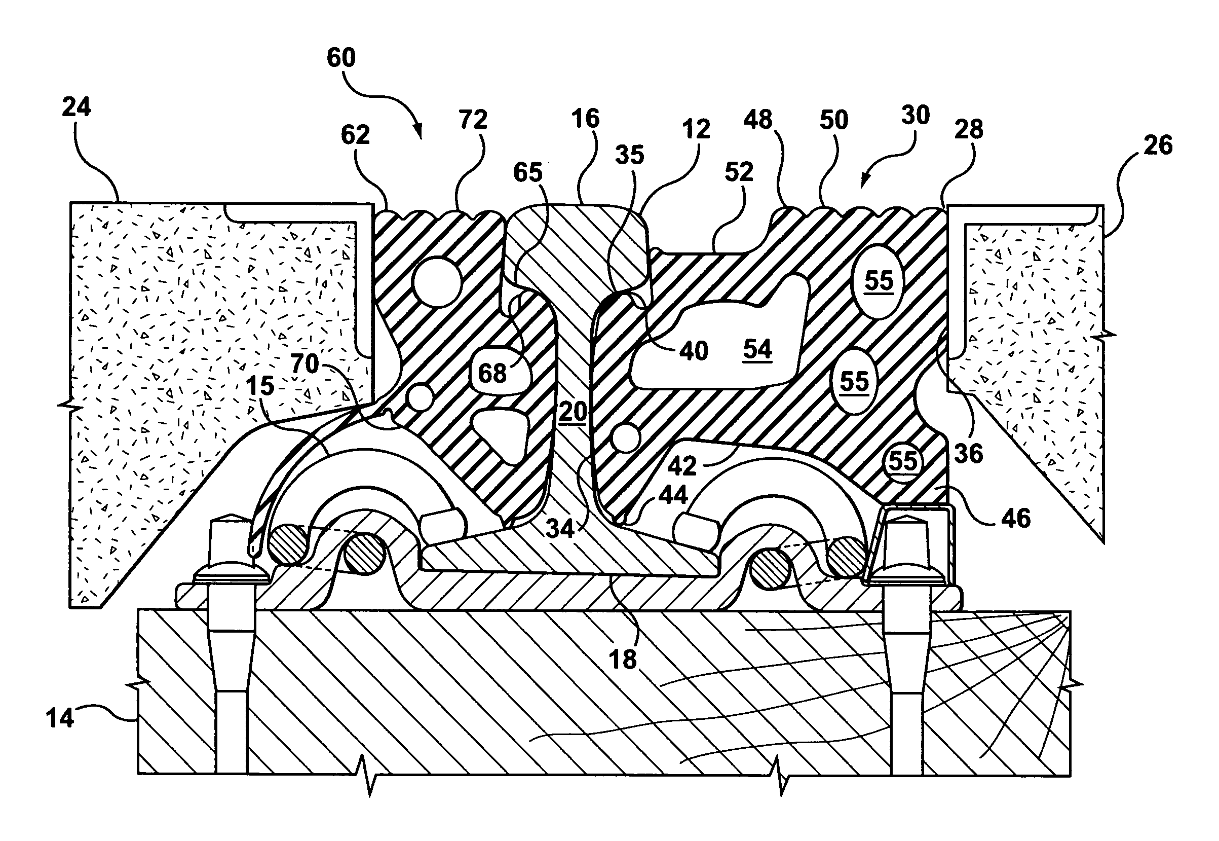
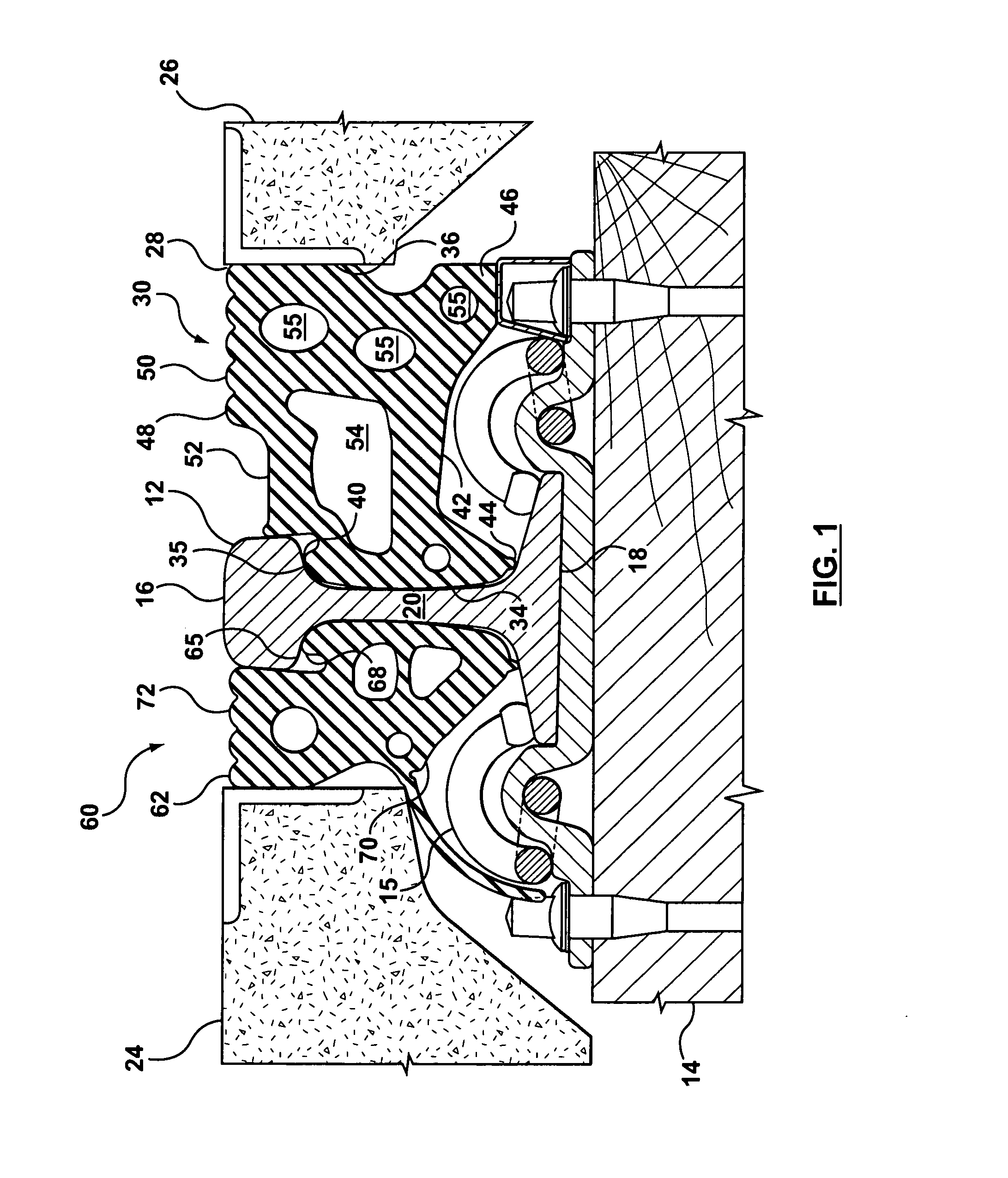
[0020]Referring now to the drawings, there is shown in FIG. 1 a cross-sectional view of a portion of a railway crossing structure incorporating a rail seal according to an example embodiment of the present disclosure. While the description may refer generally to a railway crossing structure, it will be understood that the present disclosure is not limited specifically to railroad crossings, but is also intended to cover various types of rail crossings such as streetcar crossings as well.

[0021]The railway crossing structure shown in FIG. 1 includes two parallel rails 12 (only one of which is shown) which are anchored in place by transverse members or rail ties 14 and secured with rail clips 15 to ensure that a consistent distance or gauge is maintained between the rails 12 along the length of the track. The rail 12 is generally in the form of a modified I-beam, with each rail 12 having a rail head 16, a base flange 18 and a web portion 20 interconnecting the rail head 16 and the base...


PUM


Abstract

A rail seal for sealing the gap between a rail and a concrete panel in a railroad crossing so as to provide a generally even or level surface for vehicular or pedestrian traffic while still providing an appropriate rail structure for receiving and guiding the train wheels along the tracks is provided. More particularly, the upper surface of the rail seal is formed with a recessed portion or flangeway for receiving the flanged-end of a train. The flangeway or recessed portion, however, is formed so that the surface of the flangeway lies in a plane above the bottom of the rail head but below the upper surface of the rail head, thereby providing a “shallow” flangeway. The provision of a “shallow” flangeway helps to reduce the risks associated with vehicular and / or other pedestrian traffic that must access or cross the railroad tracks. Specifically, the shallow flangeway helps to prevent the heels of pedestrian shoes or the smaller width bicycle, stroller or wheelchair wheels from becoming trapped in the gaps typically associated with railroad crossing structures.

Description

TECHNICAL FIELD[0001]The present disclosure relates generally to a rail seal for railroad crossings. More particularly, the invention relates to an elastomeric rail seal for sealing the space between a rail and the surrounding platform or road surface or road bed.BACKGROUND[0002]Railroad or streetcar tracks generally consist of two parallel steel rails that are anchored perpendicularly to tie members (i.e. rail ties) for maintaining a consistent distance or gauge between the two rails. Train or streetcar wheels are generally in the form of conical, flanged wheels with the smaller diameter end of the wheel being located on the outside of the rail and the larger diameter, flanged-end of the wheel being located on the inner or “gauge” side of the rail as the train or streetcar travels over the tracks. The train wheels run along the upper surface of the steel rails with the flanged inner end or larger diameter end of the wheel being guided along the inside edge of the track.[0003]The de...

Claims


Application Information

Patent Timeline
IPC IPC(8): E01B21/00
CPCE01C9/04E01B26/00
Inventor BURKHARDT, BRUCE E.ELLIS, RICHARD T.
Owner POLYCORP
Why Eureka
Try Eureka