
Mobile communication base station radio frequency signal sector switching system

Inactive Publication Date: 2011-12-29
WUXI BOOU ELECTRONICS TECHNOLOGICAL
View PDF3 Cites 3 Cited by
  • Summary
  • Abstract
  • Description
  • Claims
  • Application Information

AI Technical Summary

Benefits of technology

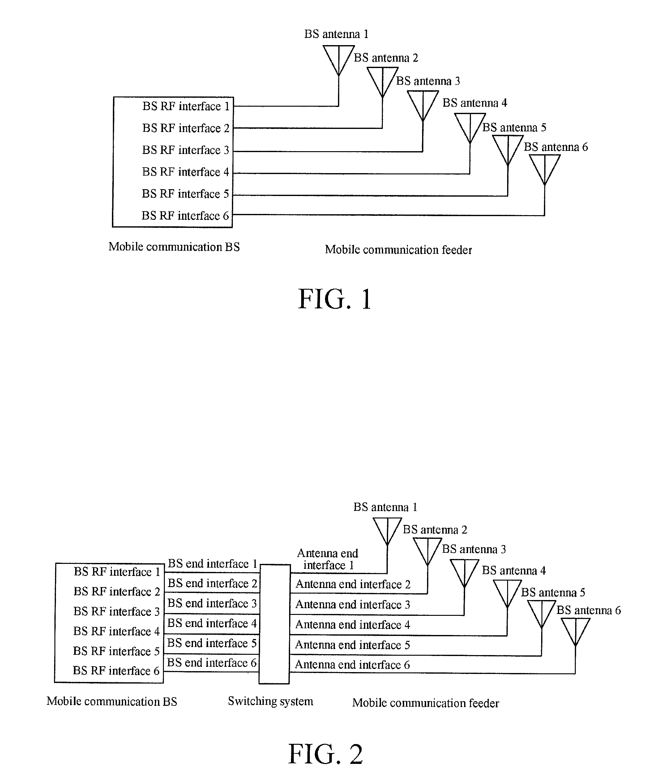
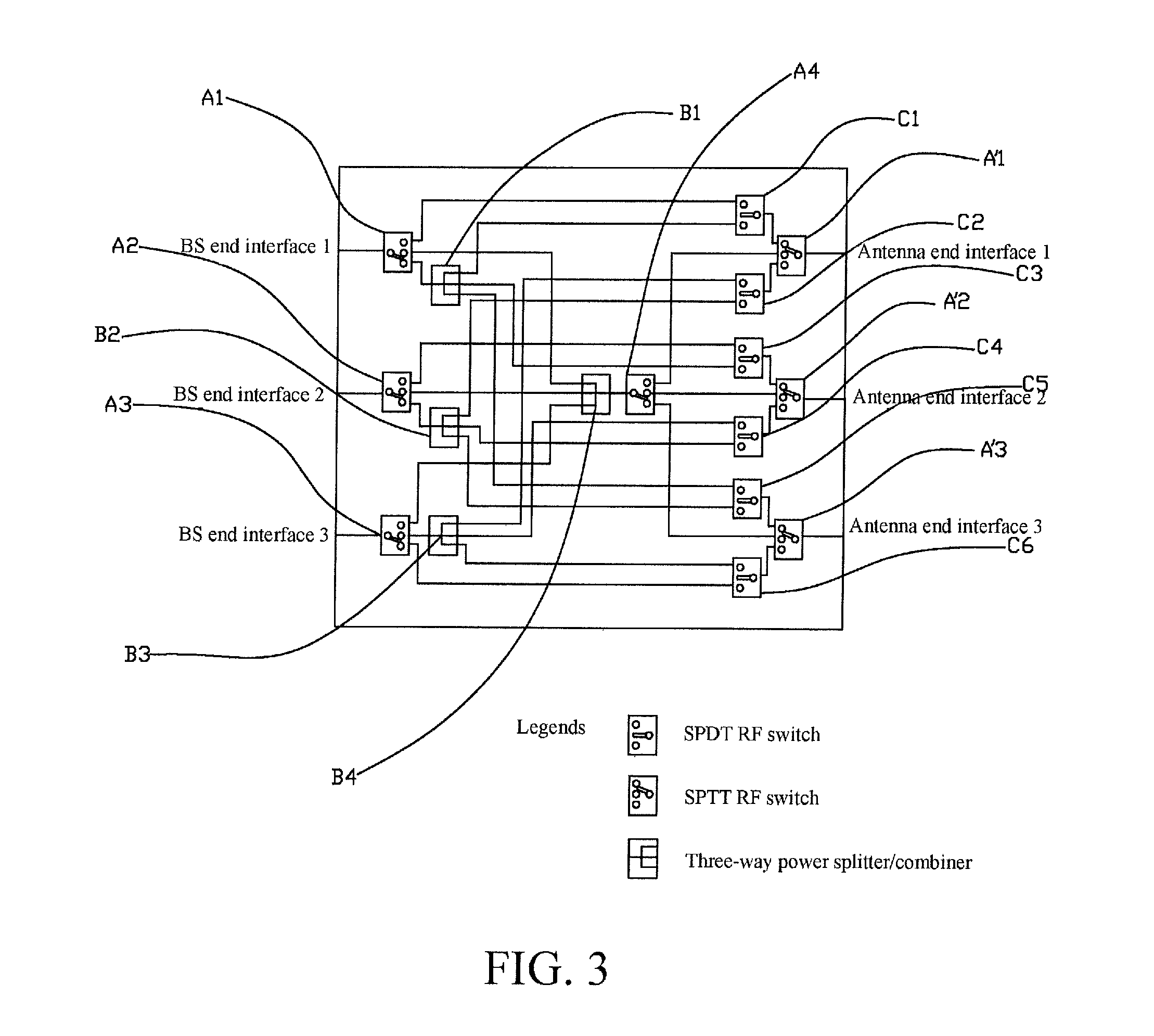
[0008]A mobile communication BS RF signal sector switching system is provided. The switching system is disposed between BS RF interfaces of a wireless communication BS and BS antennas, the switching system includes BS end interfaces connected to the three BS RF interfaces in the wireless communication BS, antenna end interfaces connected to the three BS antennas, and a switching circuit between the BS end interfaces and the antenna end interfaces, enabling any BS end interface to be electrically connected to one, two, or three antenna end interfaces at the same time, and enabling any antenna end interface to be electrically connected to one, two, or three BS end interfaces at the same time.
[0024]In a mobile communication BS RF signal sector switching system of the present invention, deployment of a carrier frequency load in a wireless communication BS can be controlled through RF switches, thereby achieving an effect that BS RF interfaces 1, 2, and 3 can transmit and receive signals through any one, two, or three BS antennas of BS antennas 1, 2, and 3.
[0026]1. With original BS antenna configurations unchanged, a carrier frequency of an idle sector is deployed to a sector with heavy traffic in the same BS, thereby achieving best use of a carrier frequency resource, increasing a channel utilization rate of an idle sector, reducing cases of channel congestion of a sector of heavy traffic, and improving quality of service of a mobile communication BS.

Problems solved by technology

When a frequency of an electromagnetic wave is lower than 100 kilohertzs (khz), the electromagnetic wave is absorbed by the ground, and cannot achieve effective transmission.
In this way, the number of users in each BS antenna coverage area may change, so that the number of clients in some coverage area may be usually very small, and a carrier frequency resource becomes idle; however, the number of users in some coverage area is very large, and a carrier frequency resource is fully loaded or overloaded.
Therefore, in practice, a carrier frequency resource is redundantly configured, which greatly wastes the carrier frequency resource in a BS system, and the wasting inevitably exists due to the current universal one-to-one antenna-feeder connection technology.

Method used


Image

  • Mobile communication base station radio frequency signal sector switching system
  • Mobile communication base station radio frequency signal sector switching system
  • Mobile communication base station radio frequency signal sector switching system

Examples


Embodiment Construction

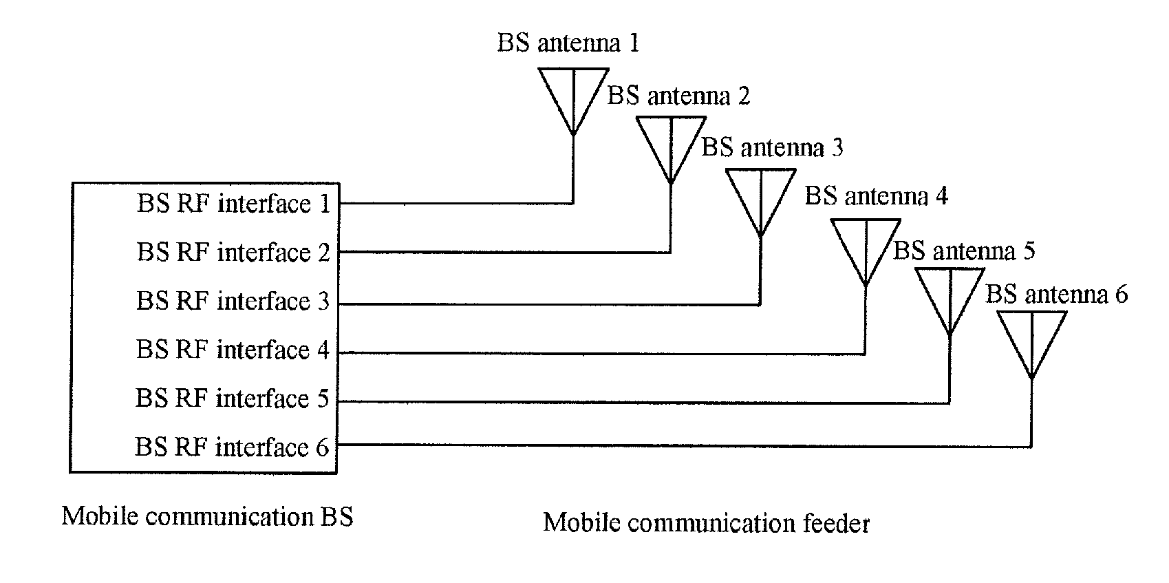
[0031]FIG. 1 illustrates an existing mobile communication BS RF signal sector coverage system, and RF cables are used to connect BS RF interfaces to BS antennas one by one respectively. That is to say, when a system is connected and mounted, a BS RF interface 1 can only transmit and receive signals through a BS antenna 1, a BS RF interface 2 can only transmit and receive signals through a BS antenna 2, and so on. In this way, the number of users in each BS antenna coverage area may change, so that the number of clients in some coverage area may be usually very small, and a carrier frequency resource becomes idle; however, the number of users in some coverage area is very large, and a carrier frequency resource is fully loaded or overloaded. Therefore, the existing mobile communication BS RF signal sector coverage system cannot make efficient use of the carrier frequency resource, and greatly wastes the carrier frequency resource.

[0032]As can be seen from FIG. 2, after a mobile commu...


PUM


Abstract

A mobile communication base station (BS) radio frequency (RF) signal sector switching system is provided. The system is disposed between BS RF interfaces of a wireless communication BS and BS antennas, and includes BS end interfaces connected to the three BS RF interfaces in the wireless communication BS, antenna end interfaces connected to the three BS antennas, and a switching circuit between the BS end interfaces and the antenna end interfaces, enabling any BS end interface to be electrically connected to one, two, or three antenna end interfaces at the same time, and enabling any antenna end interface to be electrically connected to one, two, or three BS end interfaces at the same time. With original BS antenna configurations unchanged, the mobile communication BS RF signal sector switching system can increase a channel utilization rate of an idle sector, reduce cases of channel congestion of a sector of heavy traffic, and has advantages of energy conservation and environmental protection.

Description

FIELD OF THE INVENTION[0001]The present invention relates to a mobile communication base station (BS) radio frequency (RF) signal sector switching system in the field of wireless communications technologies.RELATED ART[0002]An RF is an abbreviation of a high-frequency alternating electromagnetic wave. An alternating current alternating less than 1,000 times per second is called a low-frequency current, and an alternating current alternating more than 1,000 times per second is called a high-frequency current. An RF current is a high-frequency current. According to electronics theories, when a current passes through a conductor, a magnetic field is formed around the conductor. When an alternating current passes through a conductor, an alternating electromagnetic field is formed around the conductor, which is called an electromagnetic wave. When a frequency of an electromagnetic wave is lower than 100 kilohertzs (khz), the electromagnetic wave is absorbed by the ground, and cannot achi...

Claims


Application Information

Patent Timeline
IPC IPC(8): H04W92/00H04B7/26
CPCH04W88/08Y02D30/70
Inventor HU, GANGYUAN, XIEGUO, XIAOHONGLIU, QINGJIAN
Owner WUXI BOOU ELECTRONICS TECHNOLOGICAL
Learn More