Mass spectrometric system
a mass spectrometry and mass spectrometry technology, applied in the field of mass spectrometers, can solve the problems of limited mass spectrometer throughput, difficult to analyze all the detected ions in tandem mass spectrometry, and limited time duration in which ions are generated for tandem mass spectrometry, so as to enhance analysis throughput and enhance the effect of s/n ratio
- Summary
- Abstract
- Description
- Claims
- Application Information
AI Technical Summary
Benefits of technology
Problems solved by technology
Method used
Image
Examples
first embodiment
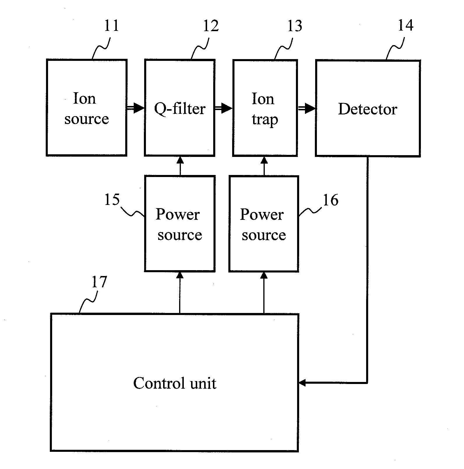
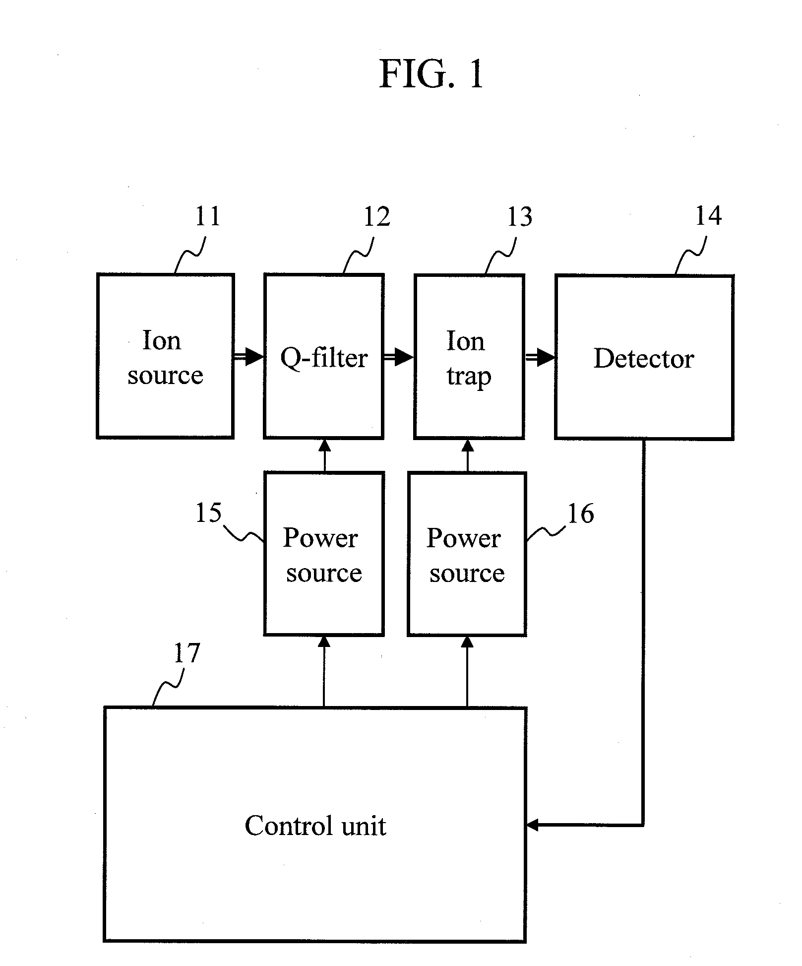
[0046]FIG. 1 is a block diagram of an embodiment of a mass spectrometric device according to the present invention. FIG. 4 in which no power sources and control unit are illustrated is a schematic diagram showing movement of ions in the device. Ions generated by an ion source 11 transmit through a Q filter 12 installed inside a vacuum device to be introduced to a quadrupole ion trap 13. The quadrupole ion trap 13 may be a linear ion trap formed of four rod electrodes or may be a three-dimensional quadrupole ion trap formed of a ring electrode and a pair of cap electrodes. The ions emitted from the ion trap 13 are detected with a detector 14. A power source 15 for the Q filter 12 and a power source 16 for the quadrupole ion trap 13 are controlled by a control unit 17.
[0047]In obtaining mass spectrometry data shown in FIG. 4(a), the Q filter power source 15 is controlled by the control unit 17 so that the majority of the ions can be transmitted through the Q filter 12 almost independe...
second embodiment
[0061]FIG. 9 is a block diagram of another embodiment of the mass spectrometric device according to the present invention. FIG. 10 in which no power sources and control unit are illustrated is a schematic diagram showing movement of ions in the device. This embodiment represents an example of a hybrid-type mass spectrometer in which a mass spectrometer 18 such as a time-of-flight mass spectrometer is connected to a downstream side of the quadrupole ion trap 13. In this example, the time-of-flight mass spectrometer is used as the mass spectrometer 18. However, a similar effect is obtained by using other mass spectrometers such as a Fourier transform mass spectrometer or a magnetic sector (double focusing) mass spectrometer as the mass spectrometer 18.
[0062]Ions generated by the ion source 11 transmit through the Q filter 12 installed inside the vacuum device to be introduced to the quadrupole ion trap 13. In obtaining mass spectrometry data shown in FIG. 10(a), the power sources 15 a...
third embodiment
[0067]FIG. 11 is a block diagram of still another embodiment of the mass spectrometric device according to the present invention. FIG. 12 in which no power sources and control unit are illustrated is a schematic diagram showing movement of ions in the device. This embodiment is close to the embodiment shown in FIG. 1 but shows an example of the mass spectrometric device provided with a pre-trap 19 between the Q filter 12 and the quadrupole ion trap 13. Although it is ideal to provide the pre-trap 19 which is the same as the quadrupole ion trap 13, the pre-trap 19 may be a multi-pole ion trap having a different size or a different number of pole electrodes as long as such an ion trap can accumulate the same amount of ions as the quadrupole ion trap without causing the space charge effect. A sample eluted from a liquid chromatograph 20 is introduced to the ion source 11.
[0068]As shown in FIG. 12(a), ions generated by the ion source 11 transmit through the Q filter 12 installed inside ...
PUM
 Abstract
Description
Claims
Application Information
 - R&D
- Intellectual Property
- Life Sciences
- Materials
- Tech Scout
- Unparalleled Data Quality
- Higher Quality Content
- 60% Fewer Hallucinations
Browse by: Latest US Patents, China's latest patents, Technical Efficacy Thesaurus, Application Domain, Technology Topic, Popular Technical Reports.
© 2025 PatSnap. All rights reserved.Legal|Privacy policy|Modern Slavery Act Transparency Statement|Sitemap|About US| Contact US: help@patsnap.com


