
Bone anchor comprising a shape memory element and utilizing temperature transition to secure the bone anchor in bone

a bone anchor and shape memory technology, applied in the field of surgical methods and equipment, can solve the problems of significant displacement or damage of the bone, requiring substantial effort to release the barbs from within the sheath, and limited application of nitinol technology for bone anchors, so as to reduce (or eliminate) load complications, reduce or substantially eliminate internal forces, and facilitate the loading of the barbed anchor into the sheath

Inactive Publication Date: 2011-12-22
TORNIER INC
View PDF3 Cites 46 Cited by
  • Summary
  • Abstract
  • Description
  • Claims
  • Application Information

AI Technical Summary

Benefits of technology

"The present invention is about a bone anchor that uses the temperature transition of a shape memory material to expand within a bone. The anchor has engagement elements that can be held within a sheath or inserted into the bone without a sheath. The use of shape memory alloy elements with appropriate temperature transition reduces or eliminates the internal forces exerted by the engagement elements on an overlying sheath, making it easier to insert and release the anchor. The bone anchors are particularly well suited for self-embedding insertion into bone without the use of pre-drilled holes. The invention also results in higher pull-out forces produced by such bone anchors."

Problems solved by technology

These applications of Nitinol technology for bone anchors are limited to isothermal applications of the stress-induced martensitic (SIM) properties of these shape memory alloys.
Unfortunately, the elastically deformed barbs commonly exert high forces on the inside of the sheath, with the result that significant friction is created as the sheath is withdrawn, thus requiring substantial effort to release the barbs from within the sheath.
Unfortunately, this approach requires high insertion forces and introduces the additional possibility of causing significant displacement or damage to the bone due to engagement of the barbs with the bone as the anchor is inserted.
Larger bone holes may be used to reduce the insertion forces required to install the bone anchor, but this is at the expense of reducing the holding power of the anchor within the bone due to the larger bone hole size.
Furthermore, larger bone holes increase bone trauma, due to the need to remove more bone material.

Method used


Image

  • Bone anchor comprising a shape memory element and utilizing temperature transition to secure the bone anchor in bone
  • Bone anchor comprising a shape memory element and utilizing temperature transition to secure the bone anchor in bone
  • Bone anchor comprising a shape memory element and utilizing temperature transition to secure the bone anchor in bone

Examples


Embodiment Construction

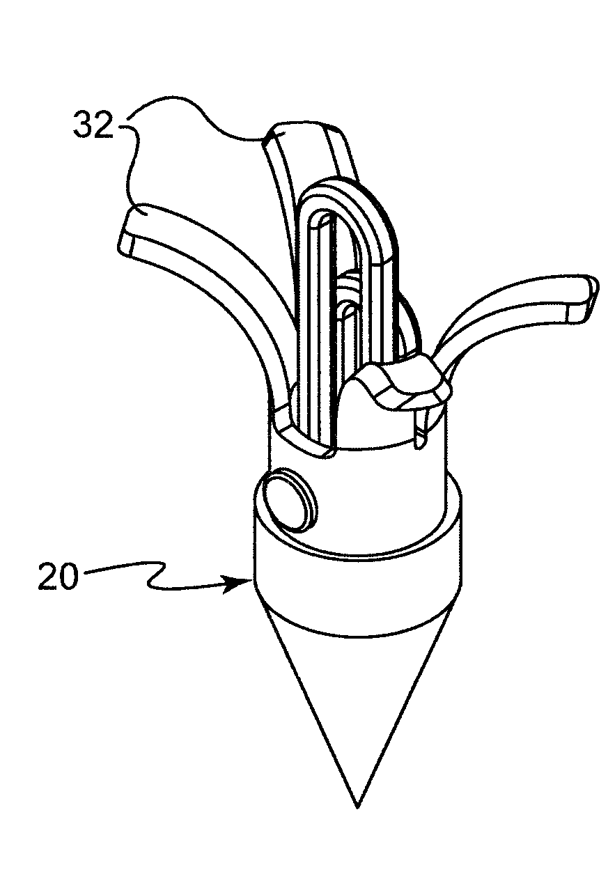
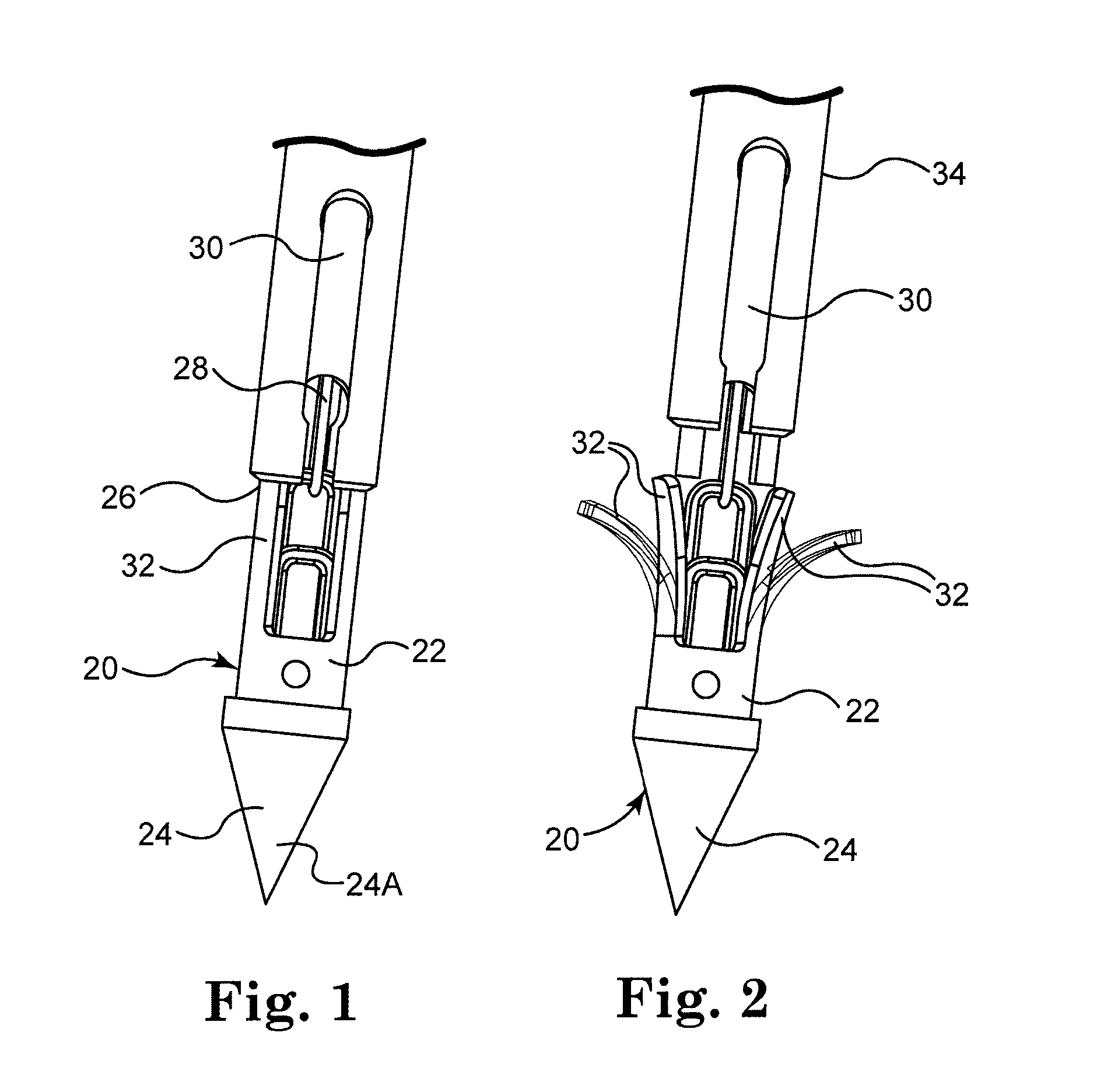
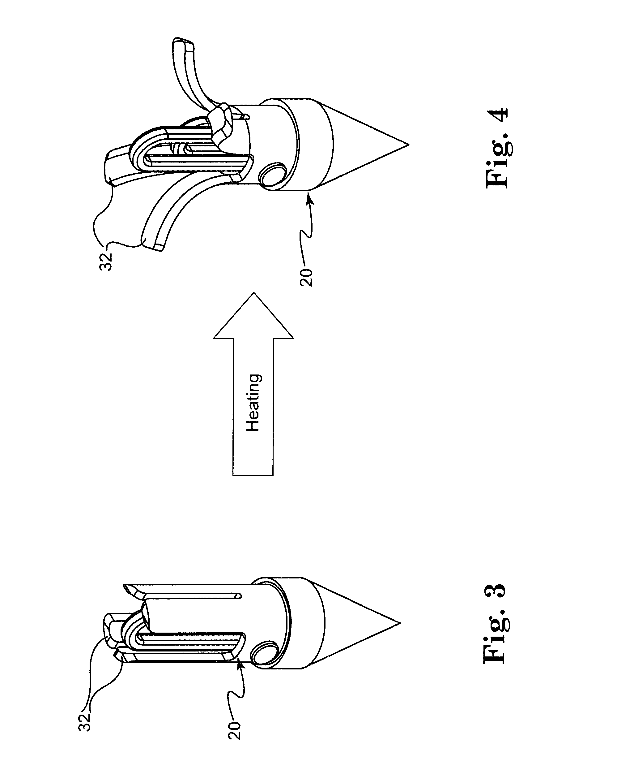
[0034]The present invention is directed to a bone anchor that includes temperature-activated engagement elements formed from a shape memory metal, such as for example a NiTi material sold by NDC Corporation of Fremont, Calif. and designated SE 508 (50.8% Ni content). As used herein, “engagement elements” refers to a temperature activated, shape memory alloy structure adapted to retain a bone anchor in bone. The engagement elements can have a variety of configurations, such as for example, barbs, hooks, serrated or threaded members, and the like.

[0035]One preferred embodiment of the present bone anchor 20 is shown in FIGS. 1 and 2. The bone anchor 20 generally includes a body 22 having a distal end 24 and a proximal portion 26. Retaining structure 28 holds the proximal portion 26 in engagement with inserter 30. In FIG. 1 a plurality of shape memory alloy engagement elements 32 are in a retracted configuration. In FIG. 2 the engagement elements 32 are in a radially expanded configurat...


PUM


Abstract

A bone anchor that uses temperature transition of a shape memory material to expand the anchor within a bone. Thermal transformation of the metallic crystal state (and hence the stress / strain properties) of shape memory alloy (e.g., Nitinol, NiTi) expands engagement elements within the bone to fix the bone anchor in place. Various self-locking assemblies for attached suture material to the bone anchor are also disclosed.

Description

[0001]The present application claims the benefit of U.S. Provisional Patent Application Ser. No. 60 / 966,087 entitled Bone Anchor Comprising a Shape Memory Element and Utilizing Temperature Transition to Secure the Bone Anchor in Bone, filed Aug. 24, 2007.FIELD OF THE INVENTION[0002]This present invention relates to a surgical methods and apparatus for attaching soft tissue to bone.BACKGROUND OF THE INVENTION[0003]Numerous devices are currently available to attach objects to bone. More particularly, screws, staples, cement and sutures have all been used to attach soft tissue (e.g., ligaments, tendons, muscles, etc.) to bone, bone to bone, and inanimate objects (e.g., prostheses) to bone.[0004]Among other things, it can be desirable to anchor a length of conventional suture in bone, so that the free end(s) of the suture can be used to attach a desired object (e.g., a ligament, a tendon, a prostheses, etc.) to the bone. This is typically done by providing a bone anchor having a length ...

Claims


Application Information

Patent Timeline
Patent Type & Authority Applications(United States)
IPC IPC(8): A61B17/04
CPCA61B17/0401A61B2017/00867A61B2017/0409A61B2017/0448A61B2017/0414A61B2017/0427A61B2017/0412
Inventor KRUMME, JOHNMCDEVITT, DENNIS
Owner TORNIER INC
Learn More