Loc device with parallel incubation and parallel DNA and RNA amplification functionality

a technology of loc devices and dna and rna, which is applied in the field of diagnostic devices, can solve the problems of slow growth of this type of testing in the clinical laboratory, reduced sensitivity, and high degree of non-specific binding, and achieves faster detection times, reduced reagent consumption and cost, and speed up molecular diagnostic assays

Inactive Publication Date: 2011-12-22
GENEASYS
View PDF7 Cites 2 Cited by
  • Summary
  • Abstract
  • Description
  • Claims
  • Application Information

AI Technical Summary

Benefits of technology

[0063]Molecular diagnostic systems based on microfluidic technologies provide the means to automate and speed up molecular diagnostic assays. The quicker detection times are primarily due to the extremely low volumes involved, automation, and the low-overhead inbuilt cascading of the diagnostic process steps within a microfluidic device. Volumes in the nanoliter and microliter scale also reduce reagent consumption and cost. Lab-on-a-chip (LOC) devices are a common form of microfluidic device. LOC devices have MST structures within a MST layer for fluid processing integrated onto a single supporting substrate (usually silico...

Problems solved by technology

Insufficient stringency can result in a high degree of nonspecific binding.
Excessive stringency can lead to a failure of appropriate binding, which results in diminished sensitivity.
Despite the advantages that molecular diagnostic tests offer, the growth of this type of testing in the clinical laboratory has been slower than expected and remains a minor part of the practice of laboratory medicine.
This is primarily due to the complexity and costs associated with nucleic acid testing compared with tests ba...

Method used


Image

  • Loc device with parallel incubation and parallel DNA and RNA amplification functionality
  • Loc device with parallel incubation and parallel DNA and RNA amplification functionality
  • Loc device with parallel incubation and parallel DNA and RNA amplification functionality

Examples


Embodiment Construction

Overview

[0599]This overview identifies the main components of a molecular diagnostic system that incorporates embodiments of the present invention. Comprehensive details of the system architecture and operation are set out later in the specification.

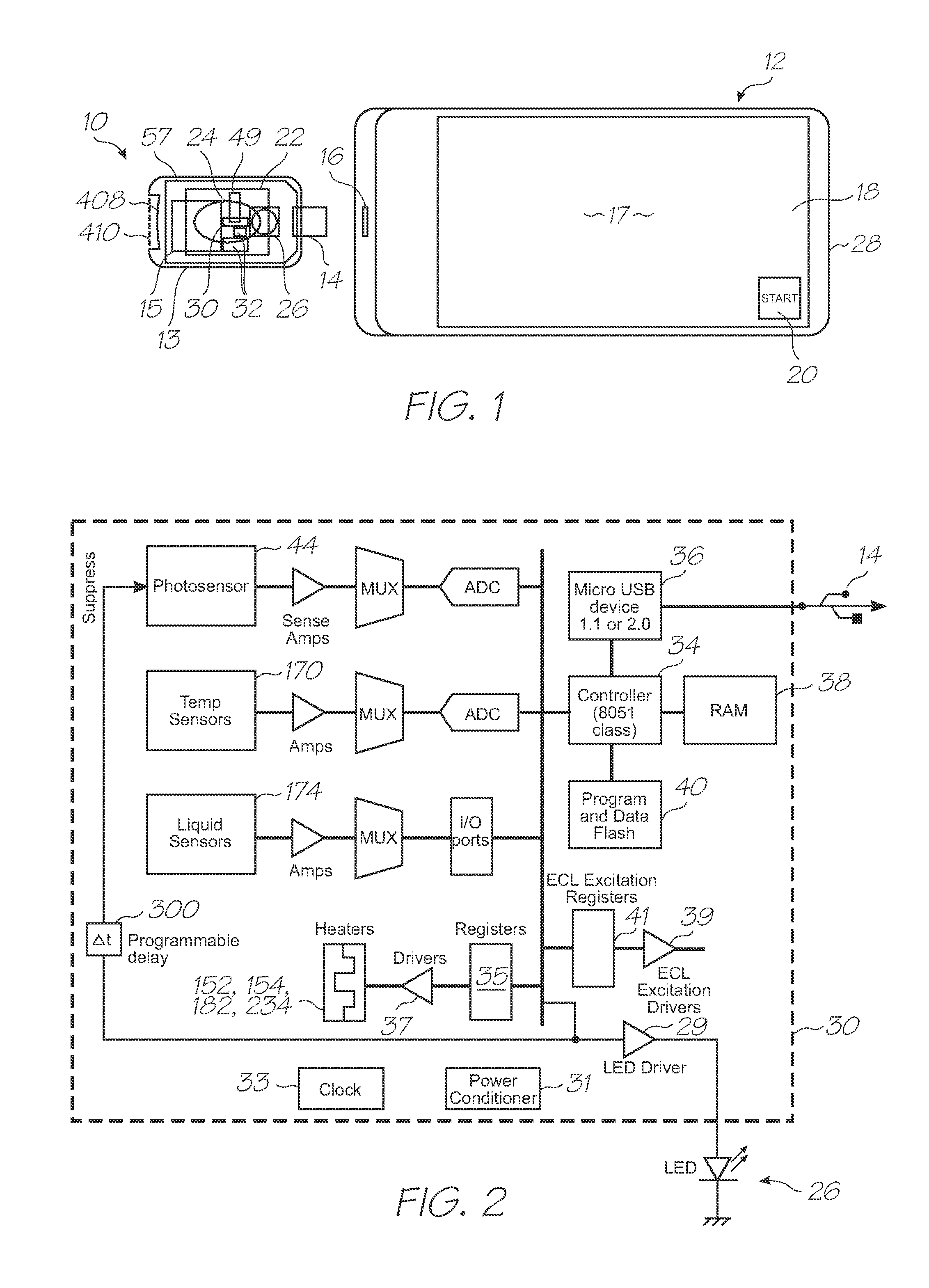
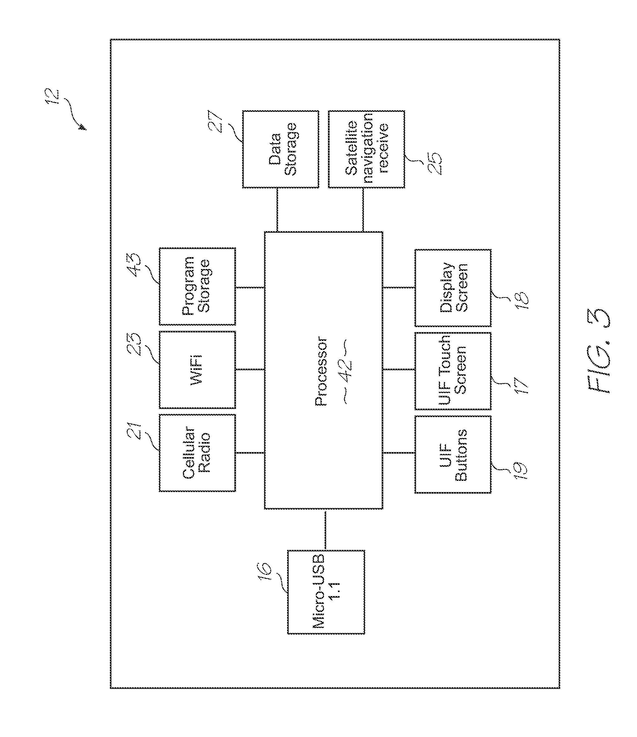
[0600]Referring to FIGS. 1, 2, 3, 123 and 124, the system has the following top level components:

[0601]Test modules 10 and 11 are the size of a typical USB memory key and very cheap to produce. Test modules 10 and 11 each contain a microfluidic device, typically in the form of a lab-on-a-chip (LOC) device 30 preloaded with reagents and typically more than 1000 probes for the molecular diagnostic assay (see FIGS. 1 and 123). Test module 10 schematically shown in FIG. 1 uses a fluorescence-based detection technique to identify target molecules, while test module 11 in FIG. 123 uses an electrochemiluminescence-based detection technique. The LOC device 30 has an integrated photosensor 44 for fluorescence or electrochemiluminescence detection...


PUM

PropertyMeasurementUnit
Areaaaaaaaaaaa
Areaaaaaaaaaaa
Temperatureaaaaaaaaaa

Abstract

A lab-on-a-chip (LOC) device for genetic analysis of a biological sample, the LOC device having an inlet for receiving the sample containing genetic material including DNA and RNA, a supporting substrate, a plurality of reagent reservoirs, a first incubation section, the first incubation section being in fluid communication with one of the reagent reservoirs containing enzymes for enzymatic reaction with the genetic material, a second incubation section, the second incubation section being in fluid communication with one of the reagent reservoirs containing enzymes for enzymatic reaction with the genetic material in parallel with the first incubation section, a first nucleic acid amplification section downstream of the first incubation section for amplifying at least some of the genetic material, and, a second nucleic acid amplification section downstream of the second incubation section for amplifying at least some of the genetic material in parallel with the first nucleic acid amplification section, wherein, the first incubation section, the second incubation section, the first nucleic acid amplification section and the second nucleic acid amplification section are all supported on the supporting substrate.

Description

FIELD OF THE INVENTION[0001]The present invention relates to diagnostic devices that use microsystems technologies (MST). In particular, the invention relates to microfluidic and biochemical processing and analysis for molecular diagnostics.CO-PENDING APPLICATIONS[0002]The following applications have been filed by the Applicant which relate to the present application:GBS001USGBS002USGBS003USGBS005USGBS006USGSR001USGSR002USGAS001USGAS002USGAS003USGAS004USGAS006USGAS007USGAS008USGAS009USGAS010USGAS012USGAS013USGAS014USGAS015USGAS016USGAS017USGAS018USGAS019USGAS020USGAS021USGAS022USGAS023USGAS024USGAS025USGAS026USGAS027USGAS028USGAS030USGAS031USGAS032USGAS033USGAS034USGAS035USGAS036USGAS037USGAS038USGAS039USGAS040USGAS041USGAS042USGAS043USGAS044USGAS045USGAS046USGAS047USGAS048USGAS049USGAS050USGAS054USGAS055USGAS056USGAS057USGAS058USGAS059USGAS060USGAS061USGAS062USGAS063USGAS065USGAS066USGAS067USGAS068USGAS069USGAS070USGAS080USGAS081USGAS082USGAS083USGAS084USGAS085USGAS086USGAS087USGAS...

Claims


Application Information

Patent Timeline
IPC IPC(8): C12M1/34
CPCB01L3/5027Y10T436/25B01L3/502738B01L7/52B01L2200/10B01L2300/023B01L2300/024B01L2300/0636B01L2300/0654B01L2300/0883B01L2300/10B01L2300/1827B01L2400/0406B01L2400/0633B01L2400/0677B01L2400/0688F16K99/003F16K99/0036G01N27/223C12Q1/68Y10T436/107497Y10T436/173845Y10T436/143333Y10T436/11Y10T436/145555Y10T436/203332Y10T436/25375B01L3/502707Y10T137/0352Y10T137/0391Y10T137/1044Y10T137/206Y10T137/2076Y10T137/2202Y02A90/10
Inventor FACER, GEOFFREY RICHARDSILVERBROOK, KIAAZIMI, MEHDI
Owner GENEASYS
Why Eureka
Try Eureka