
Closure for a beverage container

Active Publication Date: 2011-12-22
PI-DESIGN AG
View PDF12 Cites 23 Cited by
  • Summary
  • Abstract
  • Description
  • Claims
  • Application Information

AI Technical Summary

Benefits of technology

[0009]A thus designed closure for a beverage container consists of very few individual parts and is hence simple and inexpensive to produce. In particular, the closure is easy to operate for the user. For drinking purposes, the user moves the closure body from the first into the second position, whereby the discharge openings, which preferably extend in the radial direction, open up passages for the liquid. The closure body does not have to be completely removed from the insert element for this purpose. The raised, circumferential rim, which preferably forms an upwardly flared funnel region, collects the liquid escaping from the discharge openings, which liquid leaves this region again in bunched form. The rim therefore preferably has such a design with sufficiently great height that the liquid is fed in sufficiently bunched form to the mouth of the user when the beverage container is tilted for drinking purposes.
[0012]Preferably, at least two downwardly projecting, radially outward pointing hooks are arranged on the apron, which hooks prevent complete removal of the closure body from the insert element by butting against a bottom edge of the insert element as the closure is withdrawn from the insert element.
[0018]Preferably, the passages have a cross-sectional area which is variable by the position of the closure body between the first and the second position. The user can thus regulate the quantity of liquid escaping through the closure opening by choosing an optional position of the closure body between the first and the second position.
[0024]In a preferred embodiment, the vessel is of double-walled configuration. The thermal insulation of the vessel in the outward direction is thereby improved.

Problems solved by technology

Most of these beverage containers consist of a multiplicity of individual parts and have a complicated structure.
They are hence complex and expensive to produce.
The user can also gain access to the individual parts, for cleaning purposes, only with difficulty.

Method used


Image

  • Closure for a beverage container
  • Closure for a beverage container
  • Closure for a beverage container

Examples


Embodiment Construction

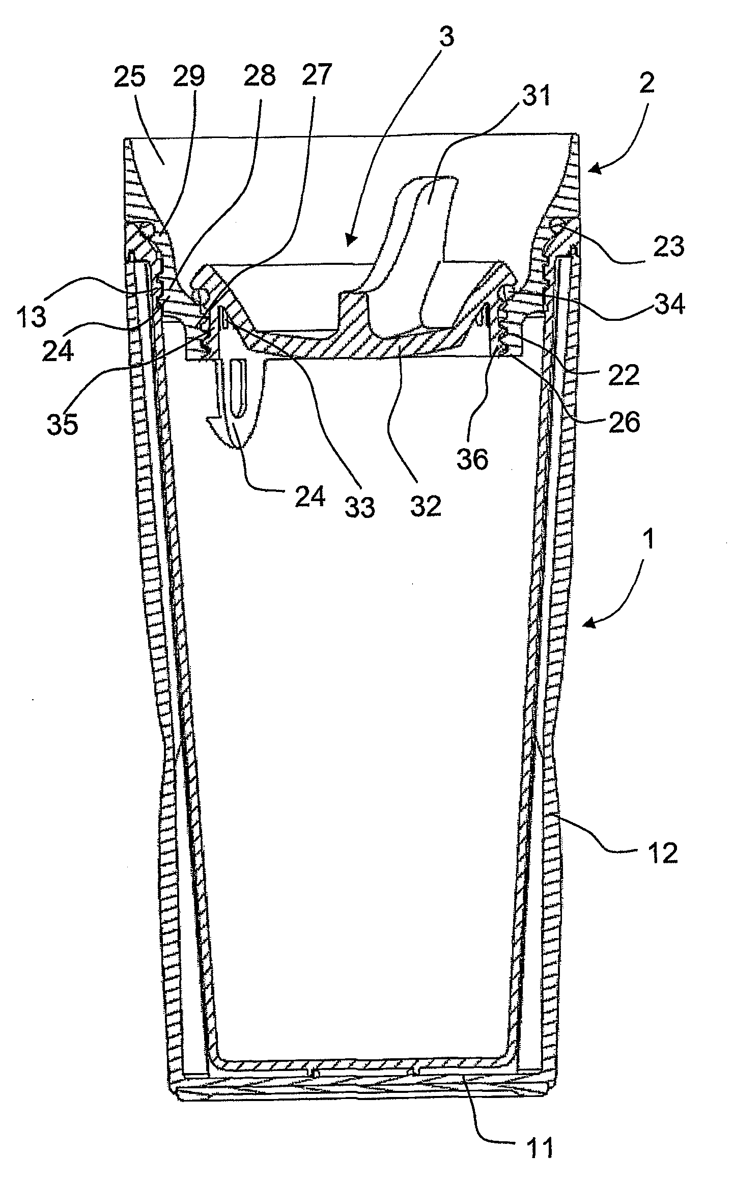
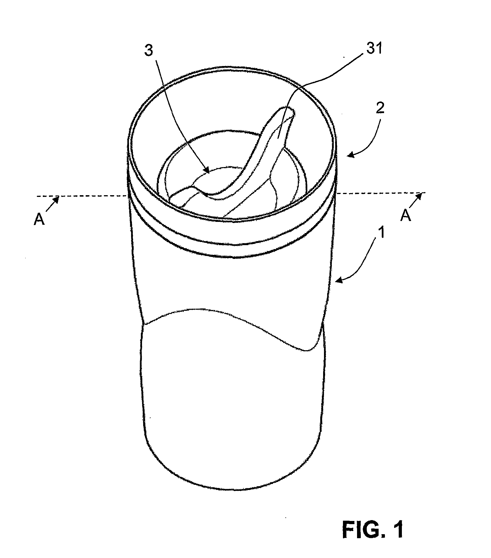
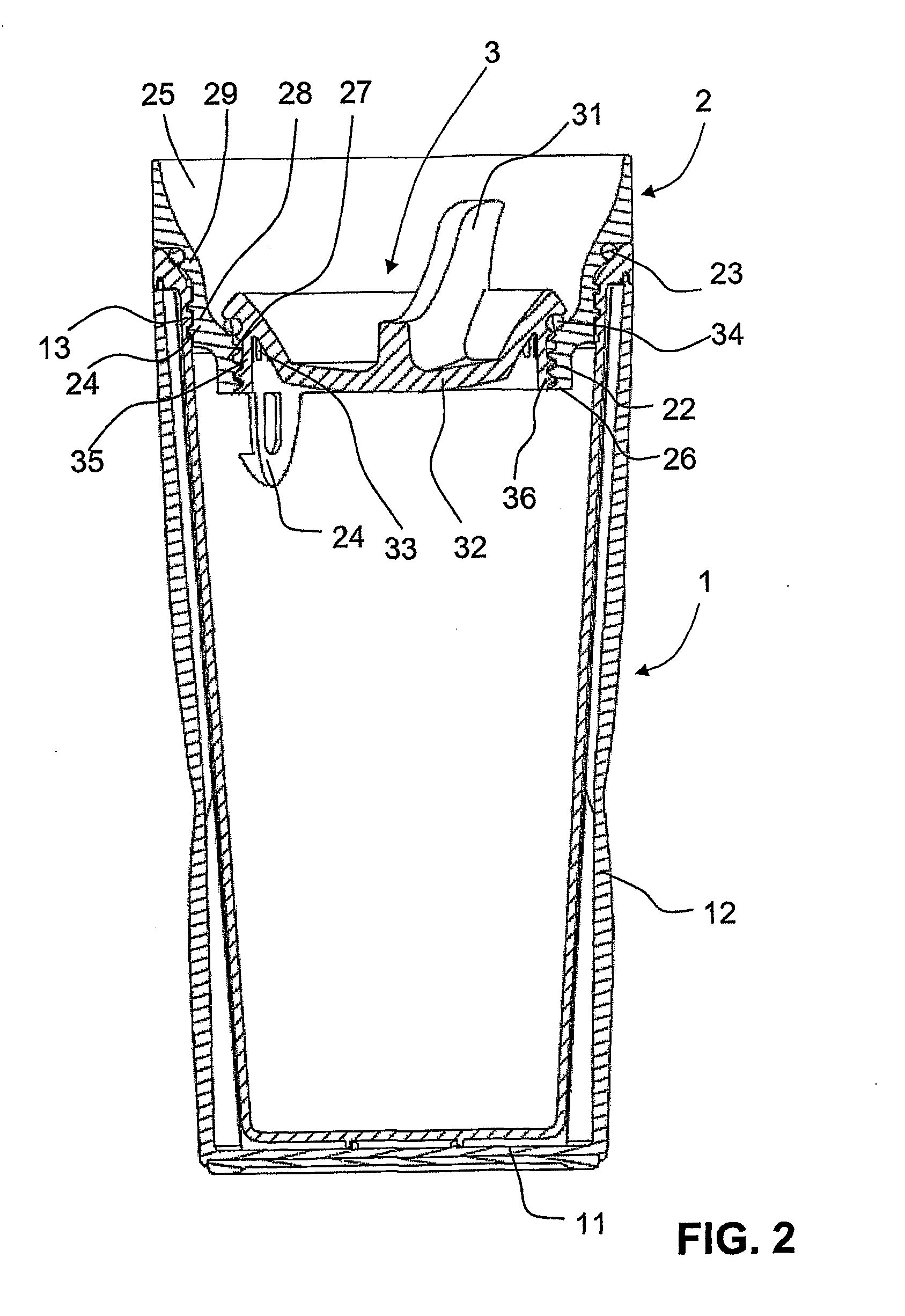
[0039]FIGS. 1 and 2 show in different representations a preferred illustrative embodiment of a beverage container having a closure according to the invention.

[0040]The beverage container has a vessel 1, an insert element 2 and a closure body 3.

[0041]The vessel 1 comprises a vessel bottom 11 and a circumferential side wall 12, the upper rim of which defines an upper opening. In the present representations, the vessel is represented as non-transparent (opaque), but it can also be transparent or translucent. It can take the form of a plastics vessel, but a vessel made of a metal or glass is also conceivable. The vessel 1 has on the outer side of its side wall 12 relief-like structures, whereby the vessel 1, on the one hand, lies better in the hand of the user and, on the other hand, looks esthetically attractive. The side wall 12 and the bottom 11 of the vessel 1 are here of double-walled design in order to improve the thermal insulation of the vessel 1. The liquid inside the vessel (n...


PUM


Abstract

A closure for a beverage container is disclosed. Said closure comprises an inserted element (2) and a closing member (3) which can be inserted into a mouth of the inserted element (2). A first engaging structure (22) mounted on the internal face of the inserted element (2) can be connected to a second engaging structure (36) arranged on the external face of the closing member (3). The inserted element (2) further has a funnel section (25) above the first engaging structure (22). The closing member (3) has a closed top surface (32), a handle element (31), and an apron (35) with outlets (33). The engaging structures (22, 36) are designed such that the closing member (3) can be moved relative to the inserted element in a vertical direction between a first position in which the closing member (3) seals the mouth and a second position in which the outlets (33) open passages for a liquid.

Description

TECHNICAL FIELD[0001]The present invention relates to a closure for a beverage container having an upwardly open vessel and to a beverage container having such a closure.PRIOR ART[0002]Beverage containers, in particular so-called “travel mugs”, which have a closure in order to keep a beverage hot or cold have long been known from the prior art. These beverage containers normally comprise a vessel having an upper opening, an internal thread being placed in the region of the opening, as well as a lid, which can be screwed into the internal thread and thus allows a sealing connection between the vessel and the lid.[0003]In order to ensure improved thermal insulation and avoid unwanted spillage of the vessel content when the user drinks from the beverage container, while on the move, for example, beverage containers in which the lid does not have to be removed from the container as a drink is taken are advantageous. The lid is therefore often designed and connected to the vessel such th...

Claims


Application Information

Patent Timeline
IPC IPC(8): A47G19/22
CPCA47G19/2272
Inventor BODUM, JORGEN
Owner PI-DESIGN AG
Learn More