
Image Processing Address Generator

a technology of image processing and address generator, applied in the field of image processing system, can solve the problems of preventing the simultaneous use of the same image frame for other driver assistance applications, preventing the use of the same sensor, and color filters with imaging sensors

Active Publication Date: 2011-12-15
MOBILEYE VISION TECH LTD
View PDF13 Cites 38 Cited by
  • Summary
  • Abstract
  • Description
  • Claims
  • Application Information

AI Technical Summary

Problems solved by technology

Expectation with 99% availability is particularly challenging to achieve in low light conditions when the lane markings are not freshly painted (have low contrast with the road) and the only light source is the car halogen headlights.
The use of color filters with imaging sensors may preclude the simultaneous use of the same image frames for other driver assistance applications.
The color mosaic filter may preclude the use of the same sensor for traffic sign recognition (TSR) or lane departure warning (LDW) because of the intensity response penalty.

Method used


Image

  • Image Processing Address Generator
  • Image Processing Address Generator
  • Image Processing Address Generator

Examples


Embodiment Construction

[0038]Reference will now be made in detail to embodiments of the present invention, examples of which are illustrated in the accompanying drawings, wherein like reference numerals refer to the like elements throughout. The embodiments are described below to explain the present invention by referring to the figures.

[0039]Before explaining embodiments of the invention in detail, it is to be understood that the invention is not limited in its application to the details of design and the arrangement of the components set forth in the following description or illustrated in the drawings. The invention is capable of other embodiments or of being practiced or carried out in various ways. Also, it is to be understood that the phraseology and terminology employed herein is for the purpose of description and should not be regarded as limiting.

[0040]By way of introduction, embodiments of the present invention take advantage of the fact that image processing is being performed involving image p...


PUM


Abstract

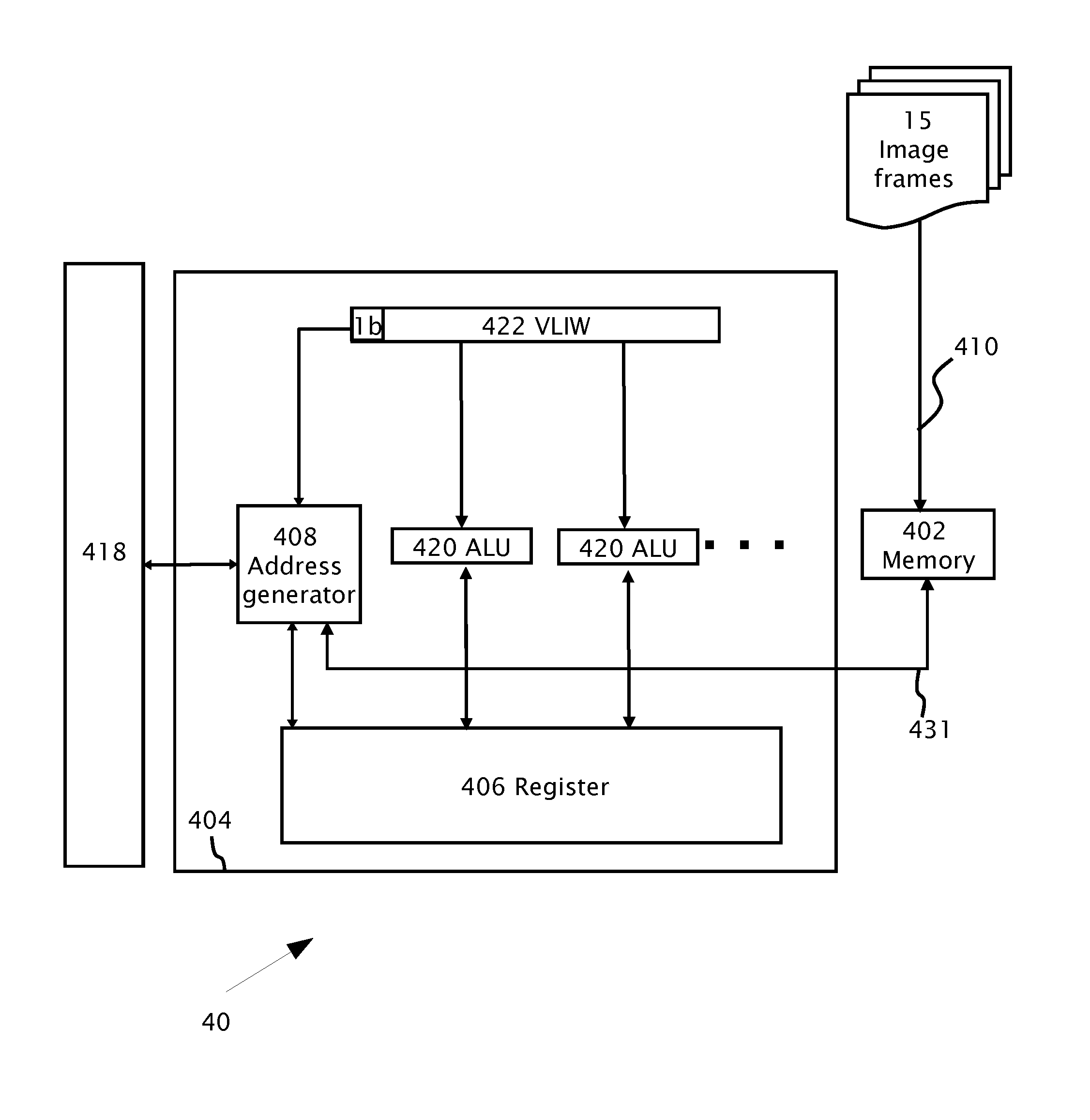
An image processing system including a vector processor and a memory adapted for attaching to the vector processor. The memory is adapted to store multiple image frames. The vector processor includes an address generator operatively attached to the memory to access the memory. The address generator is adapted for calculating addresses of the memory over the multiple image frames. The addresses may be calculated over the image frames based upon an image parameter. The image parameter may specify which of the image frames are processed simultaneously. A scalar processor may be attached to the vector processor. The scalar processor provides the image parameter(s) to the address generator for address calculation over the multiple image frames. An input register may be attached to the vector processor. The input register may be adapted to receive a very long instruction word (VLIW) instruction. The VLIW instruction may be configured to transfer only: (i) parameters for image processing calculations over the image frames by the ALU units and (ii) a single bit to the address generator.

Description

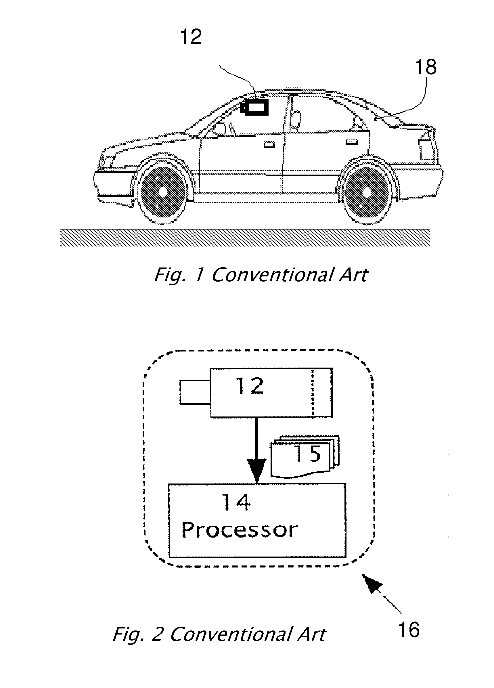
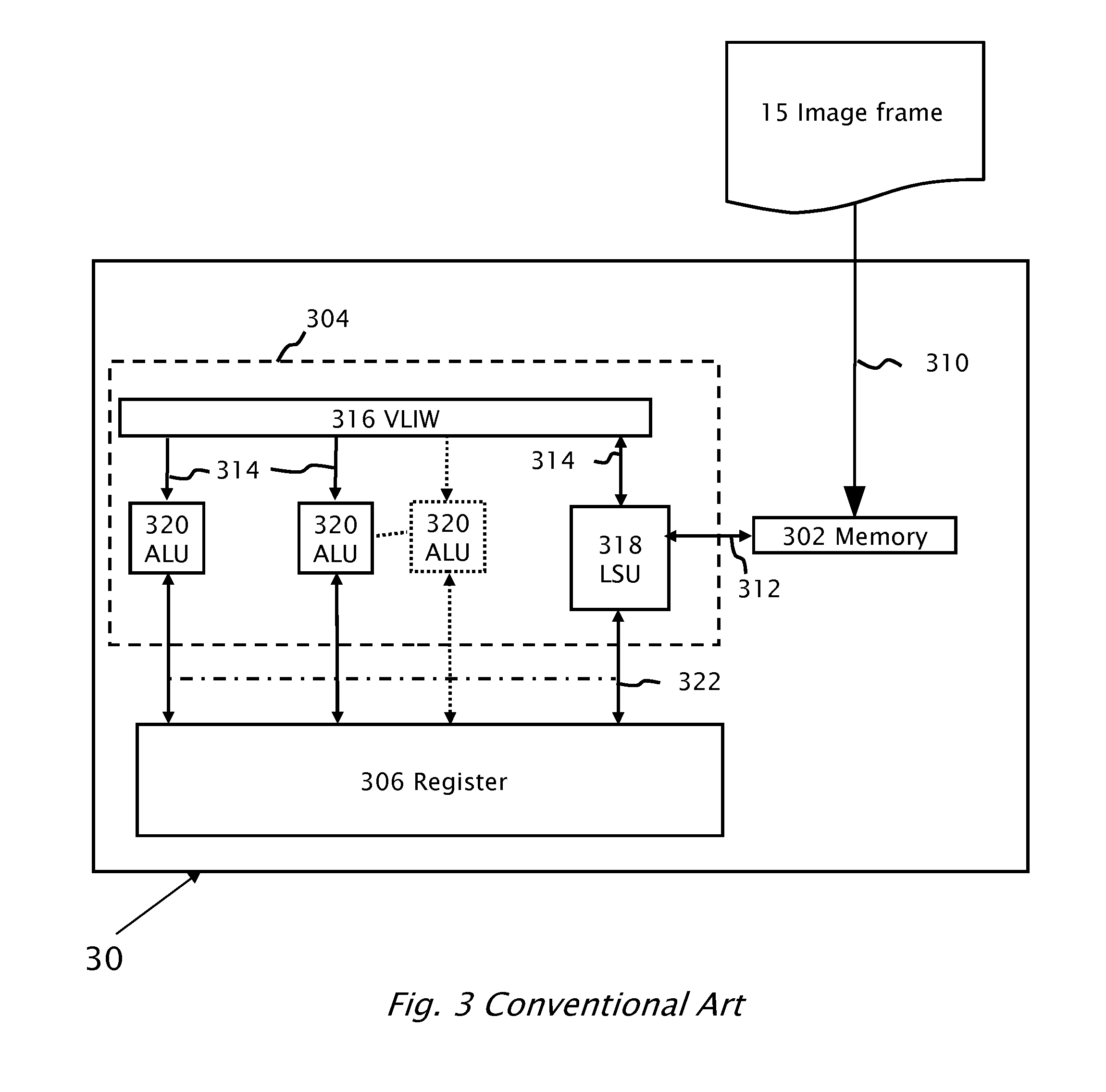
BACKGROUND[0001]1. Technical Field[0002]The present invention relates to an image processing system and specifically to an address generator used to calculate addresses so that multiple image frames or windows are processed in parallel.[0003]2. Description of Related Art[0004]Reference is made to FIG. 1 (conventional art) and FIG. 2 (conventional art) which illustrate a system 16 including a camera or image sensor 12 mounted in a vehicle 18 imaging a field of view in the forward or rear direction. Image sensor 12 typically delivers images in real time and the images are captured in a time series of image frames 15. An image processor 14 is used to process image frames 15 for processing by one or more driver assistance systems.[0005]Driver assistance systems include forward collision warning systems, lane departure warning systems, traffic sign recognition (TSR) and headlight control systems.[0006]Lane departure warning (LDW) systems are designed to give a warning in the case of unin...

Claims


Application Information

Patent Timeline
IPC IPC(8): G06K9/54G06F9/38G06F9/02G06F15/76
CPCG06F9/30043G06F9/3555G06F9/3853G06T1/20G06K9/00791G06K9/00986G06F9/3889G06V20/56G06V10/955
Inventor KREININ, YOSEFDOGON, GILSIXSOU, EMMANUELARBELI, YOSINAVON, MOISSAJMAN, ROMAN
Owner MOBILEYE VISION TECH LTD
Learn More