Method of forming polymeric microarray support

a technology of microarrays and supports, applied in the field of forming polymeric microarray supports, can solve the problem of higher background signal from autofluorescence in comparison

Inactive Publication Date: 2011-12-15
AMIC AB (SE)
View PDF1 Cites 2 Cited by
  • Summary
  • Abstract
  • Description
  • Claims
  • Application Information

AI Technical Summary

Benefits of technology

[0013]The polymeric microarray support for an optical assay arrangement comprises optical means having a depth of focus for detecting light emitted from the support. The thickness of said support varies over the surface area by a thickness variation value, and the support is provided with selected microfeatures comprising a surface enlarging pattern. The surface enlarging pattern comprises grooves arranged to have a selected depth adapted to said depth of focus of the optical means and to said thickness variation value of the support. By adapting the depth of the grooves such that the sum of said depth and of said thickness variation value substantially corresponds to said depth of focus of the optical means, an improved performance of the optical assay can be achieved, e.g. an increased signal to noise ratio. The increase of the signal-to-noise ratio is accomplished both by the increase of the signal due to the enlargement of the support surface area caused by the grooves, resulting in more binding sites, and by the reduced noise / background signal due to the reduced volume of material within the depth of focus.
[0022]Particles, e.g. solid or porous, may be provided between the pillars, which further increases the signal-to-noise ratio.
[0023]In the method of forming microfeatures comprising grooves in a polymeric microarray support of an optical assay arrangement comprising optical means having a depth of focus for detecting light emitted from said support, the thickness of said support varies over the surface area of the support by a thickness variation value. The depth of said grooves is adapted to said depth of focus and to said thickness variation value by the depth being selected such that the sum of said depth and of said thickness variation value substantially corresponds to said depth of focus, thereby causing an improved performance.

Problems solved by technology

However, a drawback with the use of polymer slides is that a higher background signal occurs from autofluorescence in comparison with glass slides.

Method used


Image

  • Method of forming polymeric microarray support
  • Method of forming polymeric microarray support

Examples


first embodiment

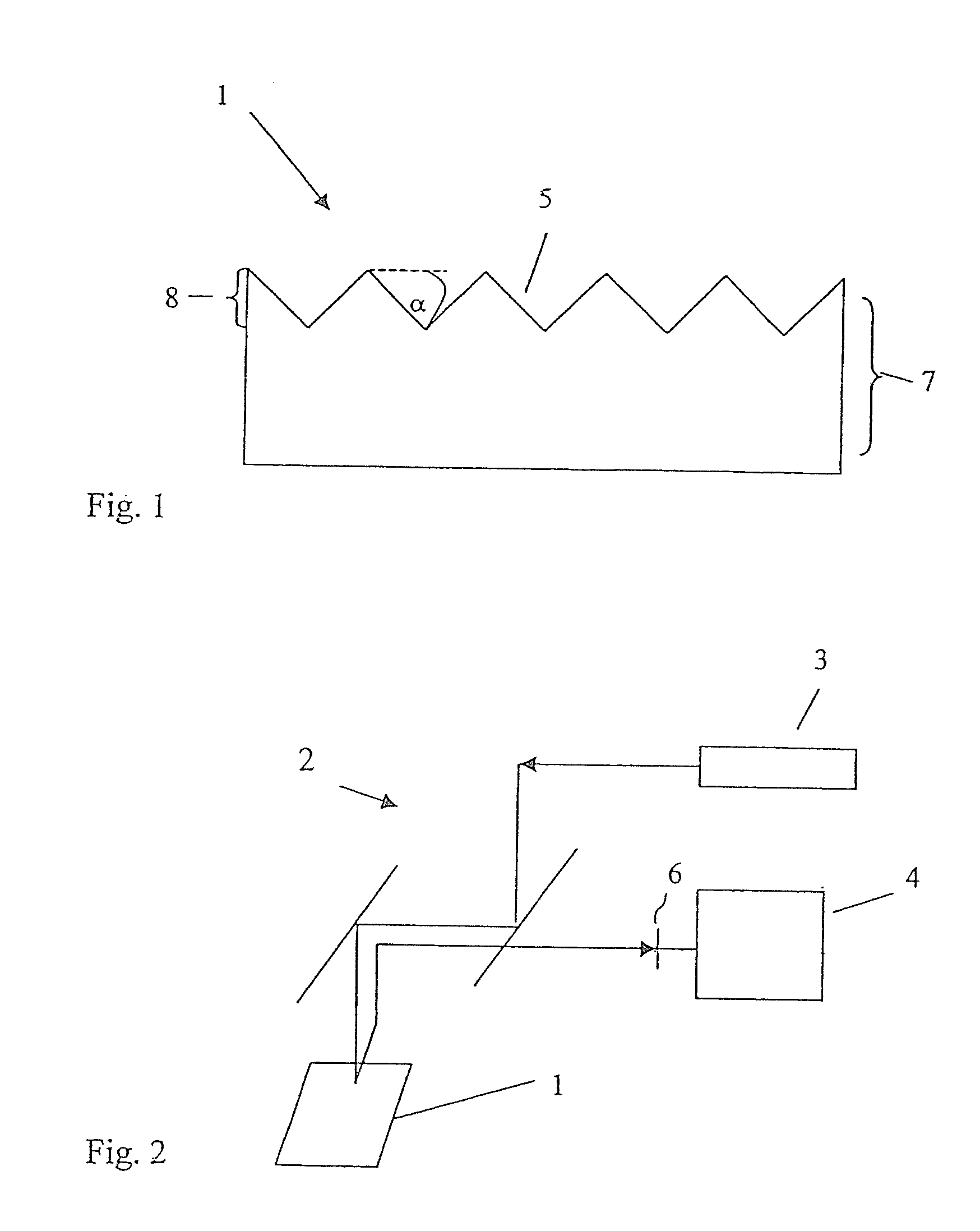
[0040]According to the invention, the microfeatures of the support comprise a surface enlarging pattern, e.g. V-grooves, the depth of the grooves being adapted to the depth of focus of the optical means of the assay arrangement, such that the sum of the selected depth of the grooves and of, the variation in the thickness of the support substantially corresponds to the depth of focus.

[0041]In an exemplary embodiment, the grooves are pyramidically shaped, the grooves master structure being anisotropically etched, in (100) silicon, resulting in a tilt angle of 55°. If the depth of focus of the optical means is 20-30 micrometers and the quality of the support slide limits the variations in the support thickness to 10-15 micrometers, the depth of the grooves, may be selected to e.g. 5-10 micrometers. Thereby, the sum of the depth of the grooves and of the thickness variation over the area of the support slide will be 15-25 micrometers.

[0042]Consequently, the sum will be well within said ...

second embodiment

[0048]According to the invention, the performance of the support is further increased by providing a reflecting layer made of a metallic, semiconducting, or a dielectric material. For visible light, a layer of silver, platinum, palladium or gold is beneficial. The thickness of the layer is preferably adapted to the desired transparency of the support, and the layer may be located on the top surface of the support substrate or in the bottom of the support. For example, a 20 nm thick gold film transmits approximately 50% of the red light. One advantage with an additional, metallic layer is that surface chemistry is easier to adopt on a metallic layer than on a polymeric surface. A further advantage is the possibility to use semi-transmitting properties of the layer, i.e. by using the specific wavelength regions of absorption found in metals, semiconductors and dielectrics to make the layer transmit certain wavelengths and reflect other wavelengths.

third embodiment

[0049]According to the invention, the support comprises grooves forming micro-pillars, i.e. cylindrical pillars. According to one exemplary embodiment, the pillars are provided with an additional layer having a larger index of refraction than the support material, thereby achieving an optical waveguide. According to a further exemplary embodiment, particles of suitable size, i.e. typically in the range between 0.1 and 50 micrometers, are located between the micropillars, which improves the signal-to-noise ratio.


PUM


Abstract

In combination, a polymeric microarray support for an optical assay arrangement, that includes an optical detection instrument having a known depth of focus for detecting light emitted from said microarray support. The polymeric microarray support has a support surface made from a polymeric support material having a thickness varying over the area of the support surface by a thickness variation value. The said support includes formed microfeatures made up of grooves arranged to have a predetermined depth at the time of forming, the groove depth being selected based on the depth of focus of the optical detection instrument and the thickness of the support. The sum of the depth for the grooves and the thickness variation value of the polymeric support surface substantially corresponds to the depth of focus of the optical detection instrument in order to reduce noise, the polymeric support surface having attached thereto probe molecules to form binding sites.

Description

CROSS REFERENCE TO RELATED APPLICATIONS[0001]This application is a divisional application of U.S. Ser. No. 10 / 556,961, filed on Nov. 15, 2005, which is a U.S. National Stage application of International Application number PCT / SE2004 / 000761, filed May 18, 2004 under 35 U.S.C. §371, which claims priority to Swedish Application Serial No. SE 0301470-1, filed May 20, 2003, the entire contents of each noted document herein being incorporated by reference.TECHNICAL OF THE INVENTION[0002]The present invention relates to an improved polymeric microarray support for an optical assay arrangement, the microarray support provided with microfeatures comprising a surface enlarging pattern. The invention also relates to an optical assay arrangement comprising an improved polymeric microarray support provided with microfeatures comprising a surface enlarging pattern, and to a method of forming microfeatures comprising a surface enlarging pattern in a polymeric microarray support for an optical assa...

Claims


Application Information

Patent Timeline
Patent Type & Authority Applications(United States)
IPC IPC(8): C40B40/00B01L3/00G01N21/25G01N21/64G01N33/543
CPCB01J2219/00527B01J2219/00576B01J2219/00605B01J2219/0061B01J2219/00637B01J2219/00659G01N33/54373B01L3/508B01L3/5088B01L2300/0636B01L2300/0654G01N21/6452G01N21/648B01J2219/00702
Inventor LINDSTROM, TOMASOHMAN, OVE
Owner AMIC AB (SE)
Why Eureka
Try Eureka