
Audio signal processing apparatus and method of controlling the same

a technology of audio signal processing and control apparatus, which is applied in the direction of frequency response correction, instruments, cameras, etc., can solve the problems of noise reduction functions, process capability, process time, process capacity, etc., and achieve the effect of reducing noise, reducing operation load of the apparatus, and effective noise reduction

Active Publication Date: 2011-12-15
CANON KK
View PDF5 Cites 26 Cited by
  • Summary
  • Abstract
  • Description
  • Claims
  • Application Information

AI Technical Summary

Benefits of technology

[0012]According to the present invention, it is possible to implement effective noise reduction while reducing the operation load of the apparatus by executing a process other than a predictive process first to reduce noise to some degree and execute the predictive process.

Problems solved by technology

However, although the techniques disclosed in Japanese Patent Laid-Open No. 04-233873 and 2006-203376 can alternately select an appropriate means from the plurality of noise reduction functions, it is impossible to use both techniques while maintaining the advantage of the plurality of noise reduction functions.
In addition, when performing a plurality of noise reduction processes using a limited resource, problems of the process time, process capability, and the like arise.
Especially, when a plurality of noise components are generated, and they are to be reduced by a predictive process of replacing all noise components with a signal calculated based on the audio signals before and after the noise generation period, as in Japanese Patent Laid-Open No. 2006-262241, the operation load increases, resulting in an increase in the cost.

Method used


Image

  • Audio signal processing apparatus and method of controlling the same
  • Audio signal processing apparatus and method of controlling the same
  • Audio signal processing apparatus and method of controlling the same

Examples


first embodiment

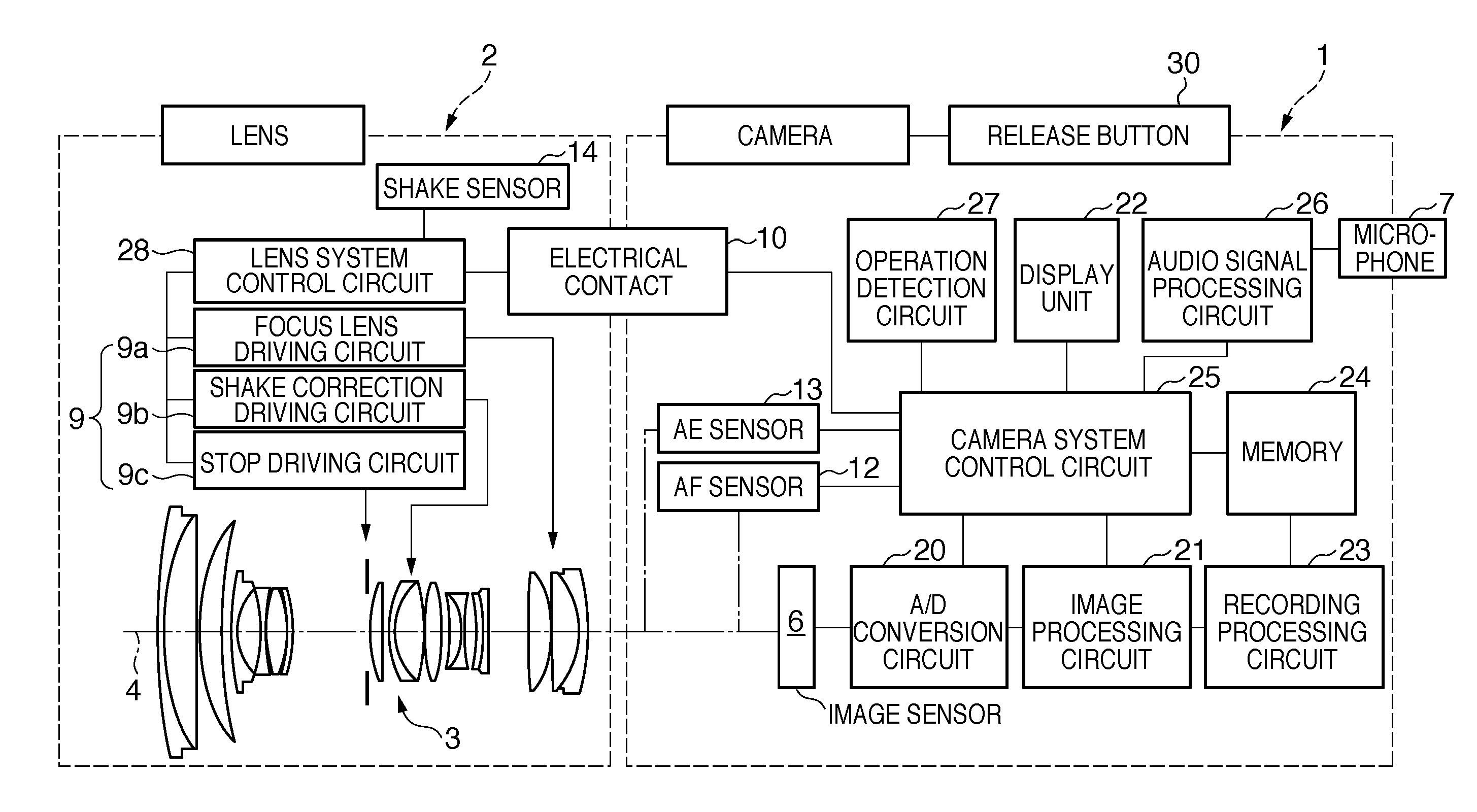
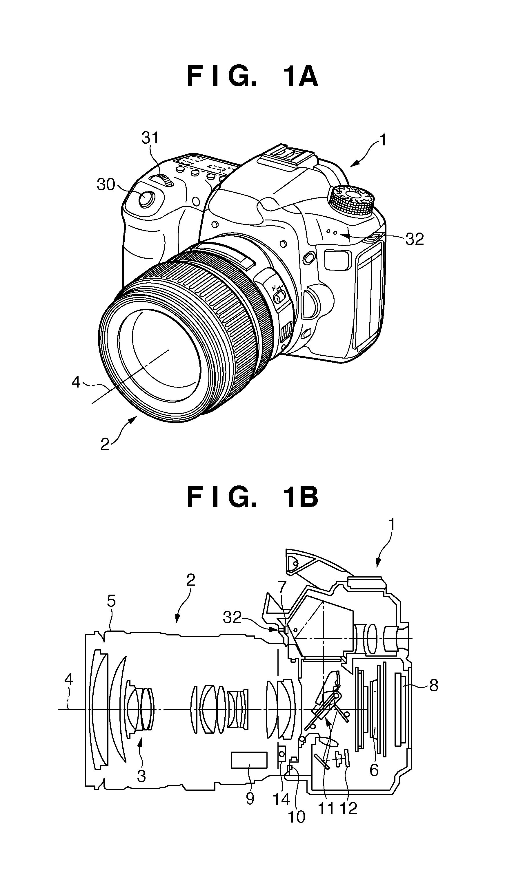
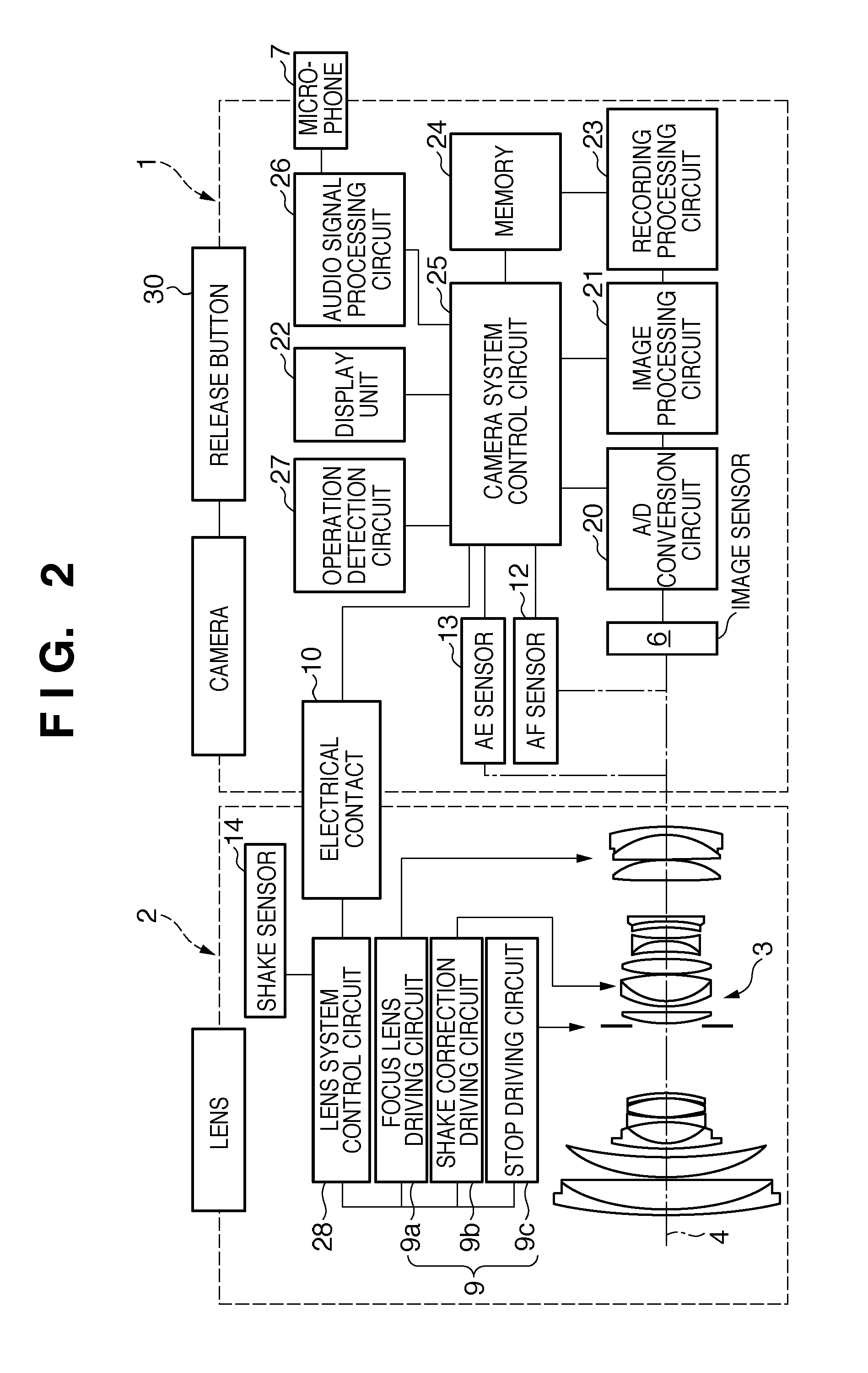
[0039]The first embodiment in which an audio signal processing apparatus of the present invention is applied to an image capture apparatus will be described below with reference to FIGS. 1A to 4C.

[0040]Referring to FIGS. 1A and 1B, reference numeral 1 denotes an image capture apparatus; 2, a photographing lens attached to the image capture apparatus 1; 3, an image capture optical system; 4, an optical axis of a lens; 5, a lens barrel; 6, an image sensor; 7, a microphone provided on the image capture apparatus 1 to pick up sound components around it; and 8, a display device provided on the rear surface of the image capture apparatus 1. Reference numeral 9 denotes an optical system driving unit configured to adjust the image capture optical system 3; 10, a contact that connects the image capture apparatus 1 and the photographing lens 2; 11, a so-called quick return mirror mechanism; 12, a focus detection unit including an AF (Auto Focus) sensor; 14, a shake sensor that detects the sha...

second embodiment

[0114]The second embodiment will be described next. A noise reduction unit 44 of this embodiment includes, out of the arrangement shown in FIG. 3, an SS process 44a, a filter process 44b, a PLC process 44e, and an LPC process 44f, and their operations and functions are the same as those described above.

[0115]The noise generation mechanism of this embodiment will be explained below. A shake correction driving circuit 9b serving as a noise source has a correction optical system (lens) drivable in biaxial directions. The shake correction driving circuit 9b corrects the camera shake by causing a driving unit (coil) to decenter the correction optical system in accordance with the detection signal from a shake sensor 14. Without current supply to the coil, the correction optical system of the shake correction driving circuit 9b decenters in the direction of gravity. When the user looks in the optical viewfinder in this state, a poor-quality image is observed. To prevent this, the correcti...


PUM


Abstract

When a first noise and second noise to be generated after the first noise are generated within a predetermined period, a noise reduction unit is controlled so as to execute a first noise reduction process for an audio signal in a period including the first noise and not to execute the first noise reduction process for an audio signal in a period including the second noise.

Description

BACKGROUND OF THE INVENTION[0001]1. Field of the Invention[0002]The present invention relates to an audio signal processing apparatus and a method of controlling the same.[0003]2. Description of the Related Art[0004]Recently, a camera capable of capturing a moving image is known as an audio signal processing apparatus. The apparatus is demanded to be, for example, insusceptible to driving sound (noise) generated upon driving the internal driving units of the apparatus. Various image capture apparatuses have been proposed to obtain the above-described characteristics.[0005]For example, Japanese Patent Laid-Open No. 04-233873 discloses selecting an appropriate filter (noise reduction function) in accordance with the noise source type. Japanese Patent Laid-Open No. 2006-203376 discloses selectively using a plurality of noise reduction functions in accordance with the noise generation time. Japanese Patent Laid-Open No. 2006-262241 discloses reducing hard disk driving noise by a techniq...

Claims


Application Information

Patent Timeline
Patent Type & Authority Applications(United States)
IPC IPC(8): H04B15/00G10L21/0216G10L21/0264
CPCH04R3/00G03B31/00H04R2499/11G11B20/24H04R3/04H04N23/00G10L21/0208
Inventor KIMURA, MASAFUMI
Owner CANON KK
Learn More