Curve Matching for Parameter Identification

a parameter identification and curve matching technology, applied in the field of system identification, can solve the problems of not observing every input, difficult control and optimization of the system, and difficult matching of a computed curve to a non-monotonically increased target curve, so as to minimize the discrepancy between the two curves

Active Publication Date: 2011-12-08
ANSYS
View PDF0 Cites 5 Cited by
  • Summary
  • Abstract
  • Description
  • Claims
  • Application Information

AI Technical Summary

Benefits of technology

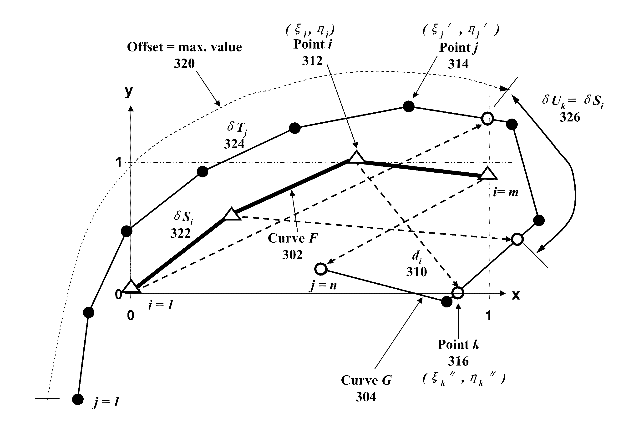
[0014]Optimization of parameter identification is achieved by adjusting the parametric inputs of a simulation model such that the discrepancy between the two curves is minimized. Because the points on the two curves to be matched are paired, matching of

Problems solved by technology

However, in a large complex system, not every input is observable.
For a system with unobservable inputs, because the output cannot be directly related to an input, control and optimization of the system is more difficult.
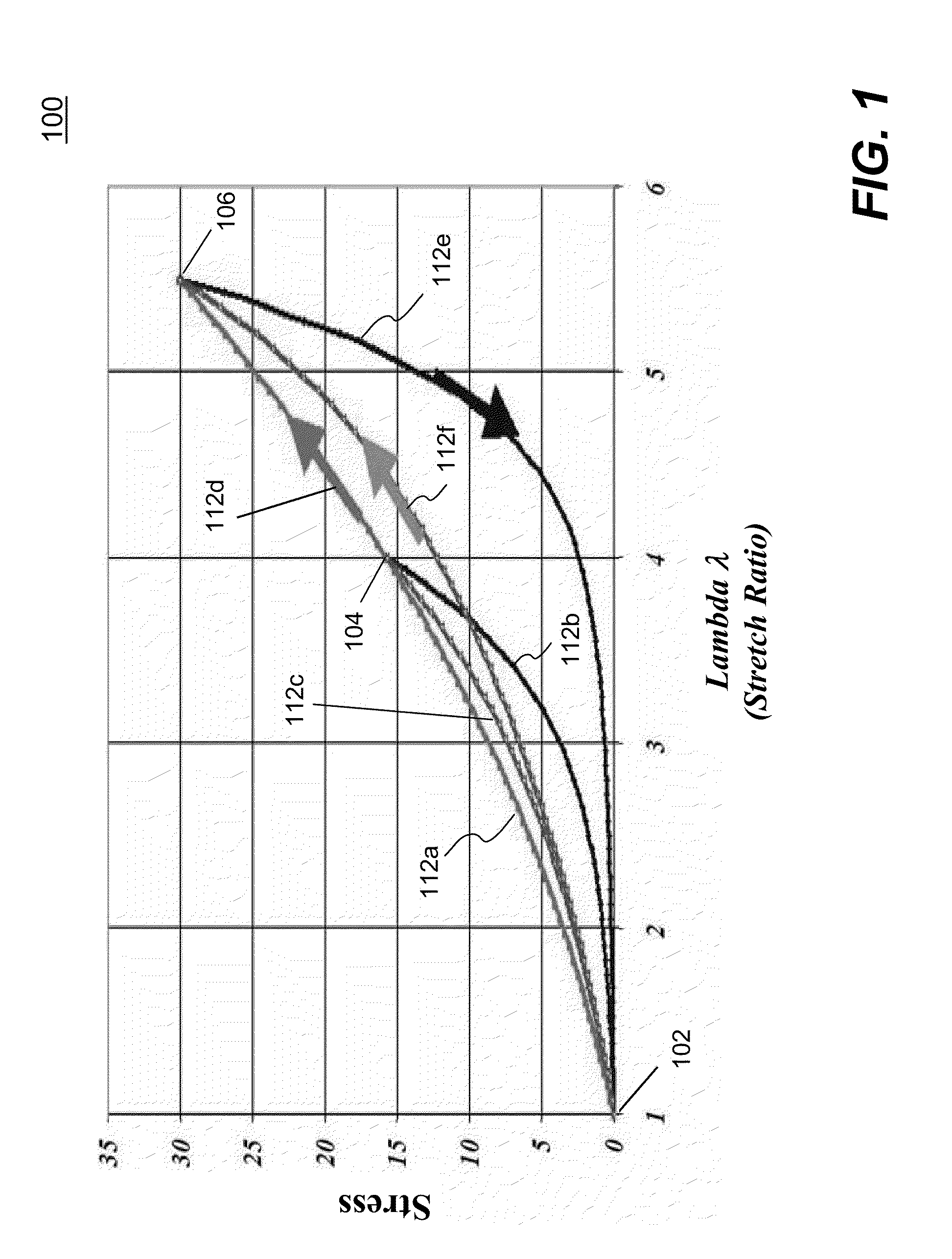
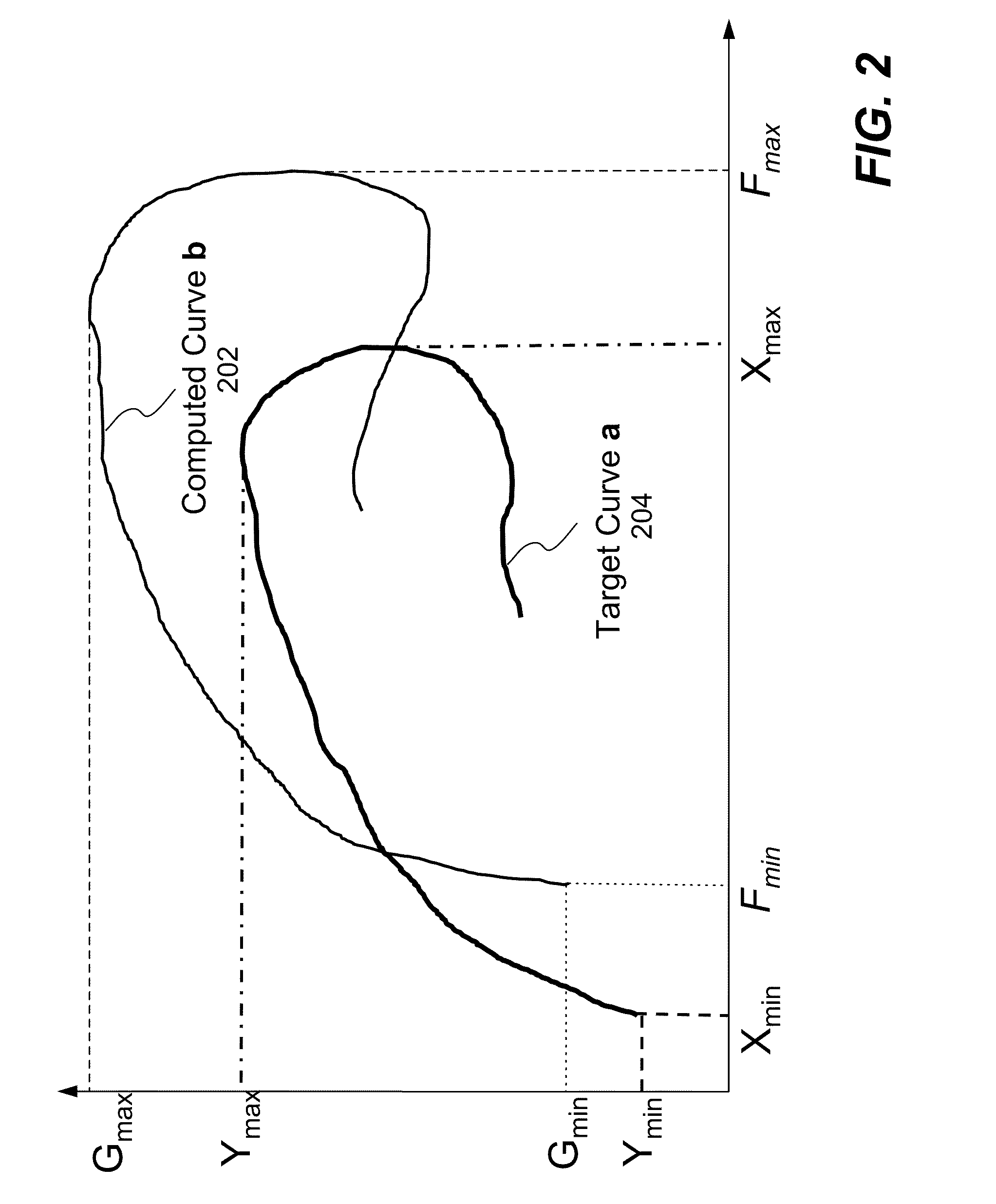
However, matching a computed curve to a non-monotonically increased target curve is not straightforward, for example, when

Method used


Image

  • Curve Matching for Parameter Identification
  • Curve Matching for Parameter Identification
  • Curve Matching for Parameter Identification

Examples


Embodiment Construction

[0028]In the following description, numerous specific details are set forth in order to provide a thorough understanding of the present invention. However, it will become obvious to those skilled in the art that the present invention may be practiced without these specific details. The descriptions and representations herein are the common means used by those experienced or skilled in the art to most effectively convey the substance of their work to others skilled in the art. In other instances, well-known methods, procedures, components, and circuitry have not been described in detail to avoid unnecessarily obscuring aspects of the present invention.

[0029]Reference herein to “one embodiment” or “an embodiment” means that a particular feature, structure, or characteristic described in connection with the embodiment can be included in at least one embodiment of the invention. The appearances of the phrase “in one embodiment” in various places in the specification are not necessarily ...


PUM


Abstract

Methods and systems for matching a computed curve to a target curve to enable realistic engineering simulations are disclosed. Optimization of parameter identification is achieved by adjusting the parametric inputs of a simulation model such that the discrepancy between the two curves is minimized. Because the points on the two curves to be matched are paired, matching of any two open curves, including hysteretic curves, can be handled. Curves that are completely set apart in their original coordinates can be merged to a common coordinate system for parameter identification without the computational instability problems. A partial matching scheme is used for mapping points defining the shorter one of the two curves to a set of mapped points on the longer one. One or more offsets from the first point of the longer curve are used for multiple attempts to find a best fit.

Description

CROSS REFERENCE TO RELATED APPLICATIONS[0001]This application is a continuation-in-part of co-pending U.S. patent application for the same title, Ser. No. 12 / 792,700, filed on Jun. 2, 2010.FIELD OF THE INVENTION[0002]The present invention generally relates to system identification used in engineering simulation of measured results, more particularly to methods for matching a computed curve to a target curve to enable the calibration of systems or material properties, so that realistic engineering simulations of the systems or materials can be carried out in a computer. Engineers and scientists use results of such simulations to improve design of engineering products.BACKGROUND OF THE INVENTION[0003]In a multiple-input dynamic model, the output is a combination of the response of each of the inputs. If the system inputs are observable, meaning the process or contribution of each input can be readily known or determined, then the output may be controlled by directly changing the relat...

Claims


Application Information

Patent Timeline
IPC IPC(8): G06F17/50
CPCG06F17/5009G06F30/20
Inventor WITOWSKI, KATHARINASTANDER, NIELEN
Owner ANSYS
Why Eureka
Try Eureka