
Spectrometric instrument

Inactive Publication Date: 2011-12-08
SEIKO EPSON CORP
View PDF16 Cites 12 Cited by
  • Summary
  • Abstract
  • Description
  • Claims
  • Application Information

AI Technical Summary

Benefits of technology

[0011]An advantage of at least one aspect of the invention is to achieve a lower power consumption or a longer life of the light source while preventing the degradation in the measurement accuracy of the colorimetric instrument, for example. Another advantage of at least one aspect of the invention is to improve in the measurement accuracy of the spectroscopic analyzer can be improved, for example.

Problems solved by technology

However, because of its large power consumption, it is required for the portable colorimetric instrument using a battery to mount a large battery.
Therefore, the shape and the weight of the colorimetric instrument increase, which makes it difficult to apply such a light source to a small-sized device superior in portability.
It should be noted that the dispersion spectrum has several bright lines in the visible range, and further, the miniaturization of the fluorescent lamp has limitations.
Therefore, in the case in which the reflectance spectrum of the measurement object is measured, the measurement error becomes large around the peak wavelength.
According to the technology described in Document 1 fails to solve the problem described above.
Further, also in the case in which the white LEDs are used for a spectroscopic analyzer, a spectroscopic camera, the presence of the discontinuous peak described above contributes to the degradation of the measurement accuracy.
If the radiance distribution of the light source shows the discontinuous peak, when, for example, the actual emission wavelength is slightly shifted from the ideal emission wavelength, the radiance varies dramatically to thereby cause the measurement error.
If the peak is reduced, it becomes difficult to cause a significant measurement error.
For example, if the variable-gap etalon filter is used as the spectroscopic element, although it is possible to obtain a simple, small-sized, and low-price spectroscopic section, the spectral accuracy is inevitably degraded compared to expensive spectroscopic elements.

Method used


Image

  • Spectrometric instrument
  • Spectrometric instrument
  • Spectrometric instrument

Examples


first embodiment

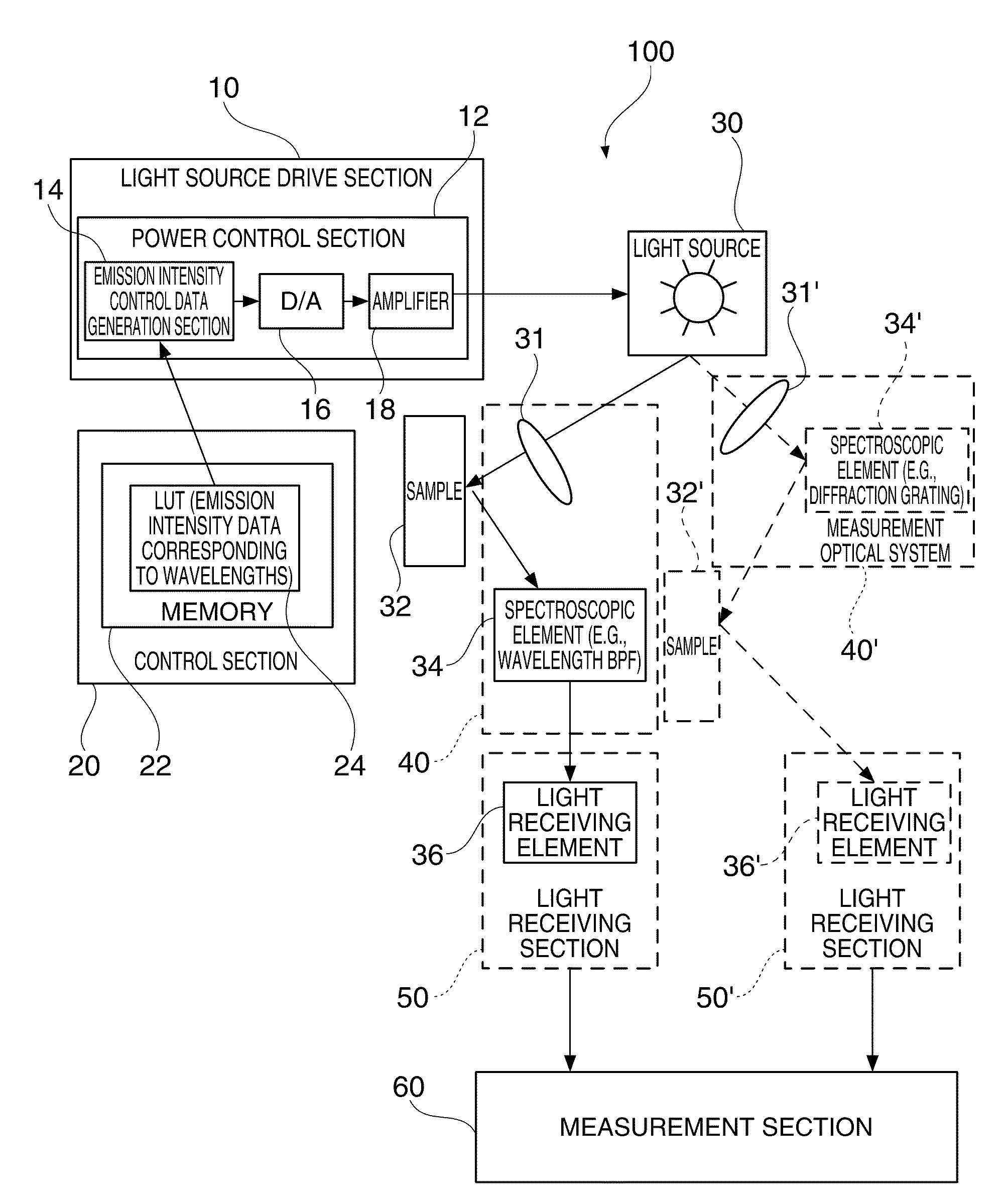
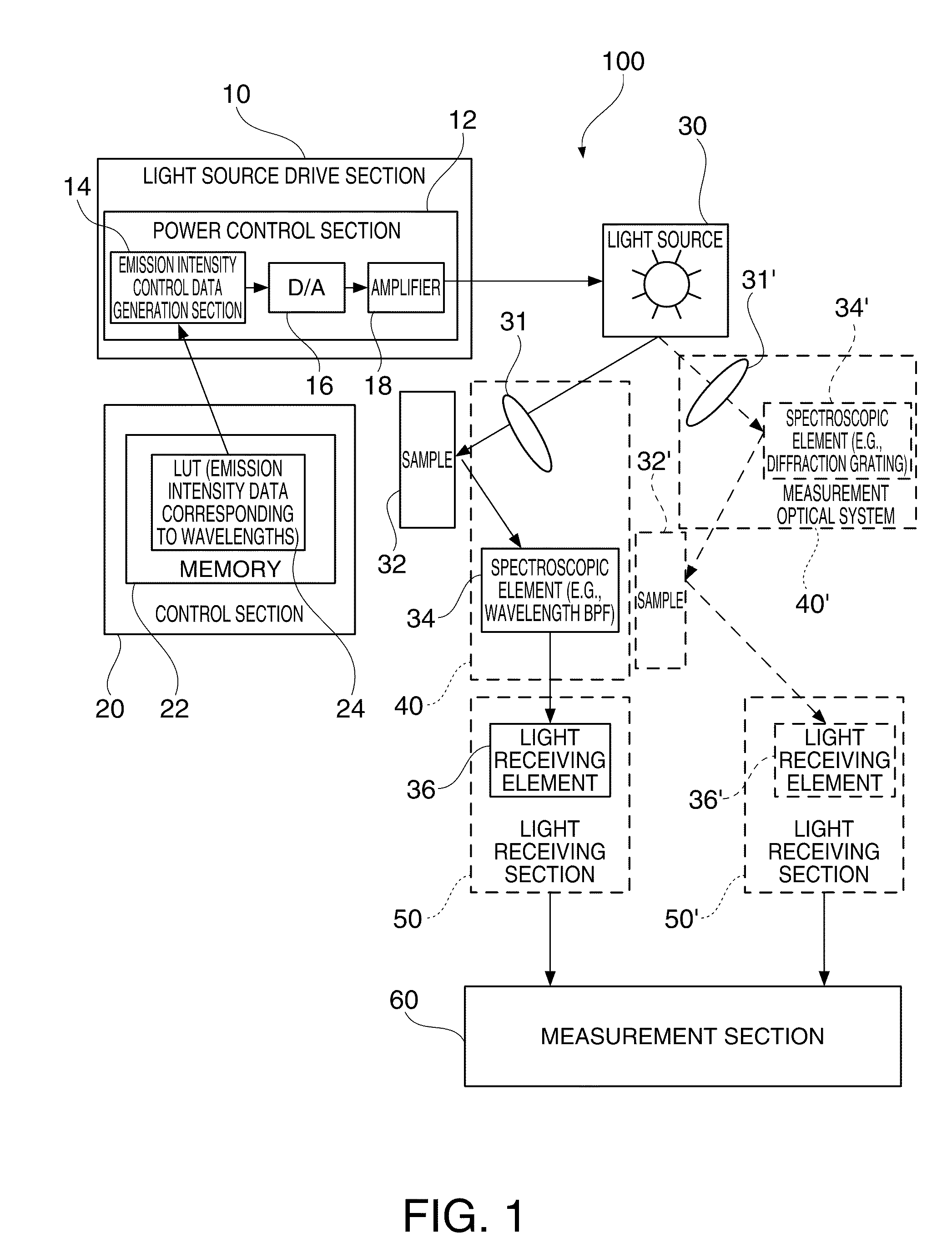
[0042]FIG. 1 is a diagram showing an example of a configuration of a spectrometric instrument according to the invention. The spectrometric instrument 100 has a light source drive section 10, a control section 20 for controlling the emission brightness (emission intensity) of the light source in correspondence with the wavelength, a light source 30, a measurement optical system 40 or 40′, a light receiving section 50, and a measurement section 60.

[0043]Specifically, the control section 20 has a memory (a control memory) 22 storing, for example, a look-up table (LUT) 24 having the emission intensity data (the control data) corresponding to the wavelength as a table.

[0044]Further, the light source drive section 10 has a emission intensity control data generation section 14 for generating the emission intensity control data based on the control data retrieved from the control memory 22, a D / A converter 16 for generating an emission intensity control signal corresponding to the emission...

second embodiment

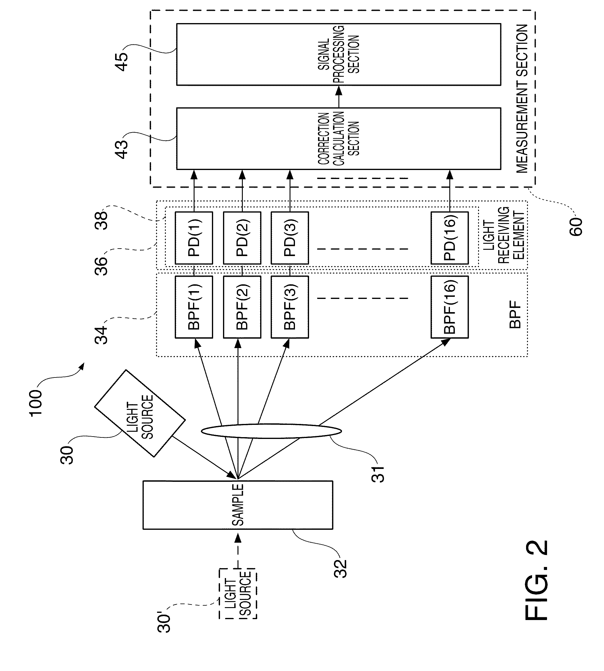
[0077]In the present embodiment, in the spectroscopic analyzer, the power control section 12 controls the power to be applied to the light source 30 so as to reduce the difference in radiance between the wavelengths of the light source 30 in the measurement wavelength band.

[0078]Thus, the difference (variation) in emission intensity between the wavelengths of the light source of the spectroscopic analyzer can be reduced. Therefore, the measurement accuracy of the spectroscopic analyzer can be improved.

[0079]Hereinafter, the present embodiment will specifically be explained using an example of measuring the reflectance spectrum (the reflectivity at the characteristic wavelengths) of chlorophyll present in a plant leaf to thereby figure out the health condition and the growing condition of the plant.

[0080]FIG. 8 is a diagram showing examples of reflectance spectra of a healthy leaf and an unhealthy leaf, respectively. In the drawing, the characteristics of the healthy leaf (a green le...

third embodiment

[0088]In the present embodiment, the power to be supplied to the light source is varied in accordance with the wavelength so as to compensate not only the variation in the radiance of the light source but also the spectral sensitivity characteristics of the light receiving element. Further, it is also possible to compensate the spectral characteristics of the measurement optical system. Thus, the measurement accuracy can further be homogenized between the wavelengths.

[0089]FIGS. 10A through 10D are diagrams for explaining an example of controlling the radiance characteristics of the light source taking the spectral characteristics of the light receiving section (detector) into consideration. FIG. 10A shows a principal configuration for measuring the spectral reflectivity of the sample 32. FIG. 10B shows an example of the spectral sensitivity characteristics of a CCD sensor as the light receiving section 50 (the light receiving element 36). FIG. 10C shows the spectral intensity (spec...


PUM


Abstract

A colorimetric instrument includes a power control section adapted to vary the power to be applied to the light source between the wavelengths in accordance with at least one of spectral characteristics of the light source, spectral characteristics of the measurement optical system, and light receiving sensitivity characteristics of the light receiving section.

Description

BACKGROUND[0001]1. Technical Field[0002]The present invention relates to a spectrometric instrument.[0003]2. Related Art[0004]As an example of a spectrometric instrument, there can be cited a colorimeter, and further, as another example thereof, there can be cited a spectroscopic analyzer for measuring the spectral reflectivity (the spectral transmission or the spectral absorption factor) of light. Further, the spectrometric instrument also includes a spectroscopic camera.[0005]As a method of representing object colors, there is widely used a representation method using the XYZ color system set by the International Commission on Illumination (CIE). As a light source for colorimetric measurement, a standard light source (including, e.g., a standard illuminant and an auxiliary illuminant set by CIE) is defined in the standard (the standard regarding measurement of object colors) set by, for example, ISO / CIE, or JIS. The standard light source denotes, for example, an artificial light s...

Claims


Application Information

Patent Timeline
IPC IPC(8): G01J3/427
CPCG01J3/10G01J3/513G01J3/51G01J3/502
Inventor SAKURAI, KAZUNORI
Owner SEIKO EPSON CORP
Learn More