
Optical navigation apparatus

a technology of optical navigation and optical axis, which is applied in the direction of static indicating devices, counting objects on conveyors, instruments, etc., can solve the problem of not being able to achieve this illumination effect, and achieve the effect of enhancing the cosmetic

Active Publication Date: 2011-12-08
CLOUD LIGHT TECH LTD
View PDF8 Cites 12 Cited by
  • Summary
  • Abstract
  • Description
  • Claims
  • Application Information

AI Technical Summary

Benefits of technology

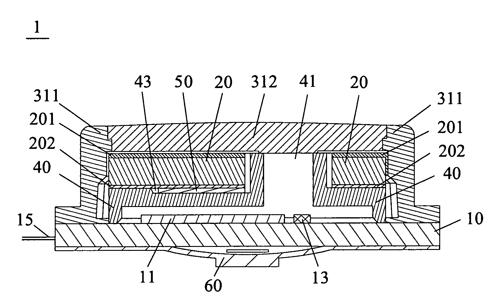
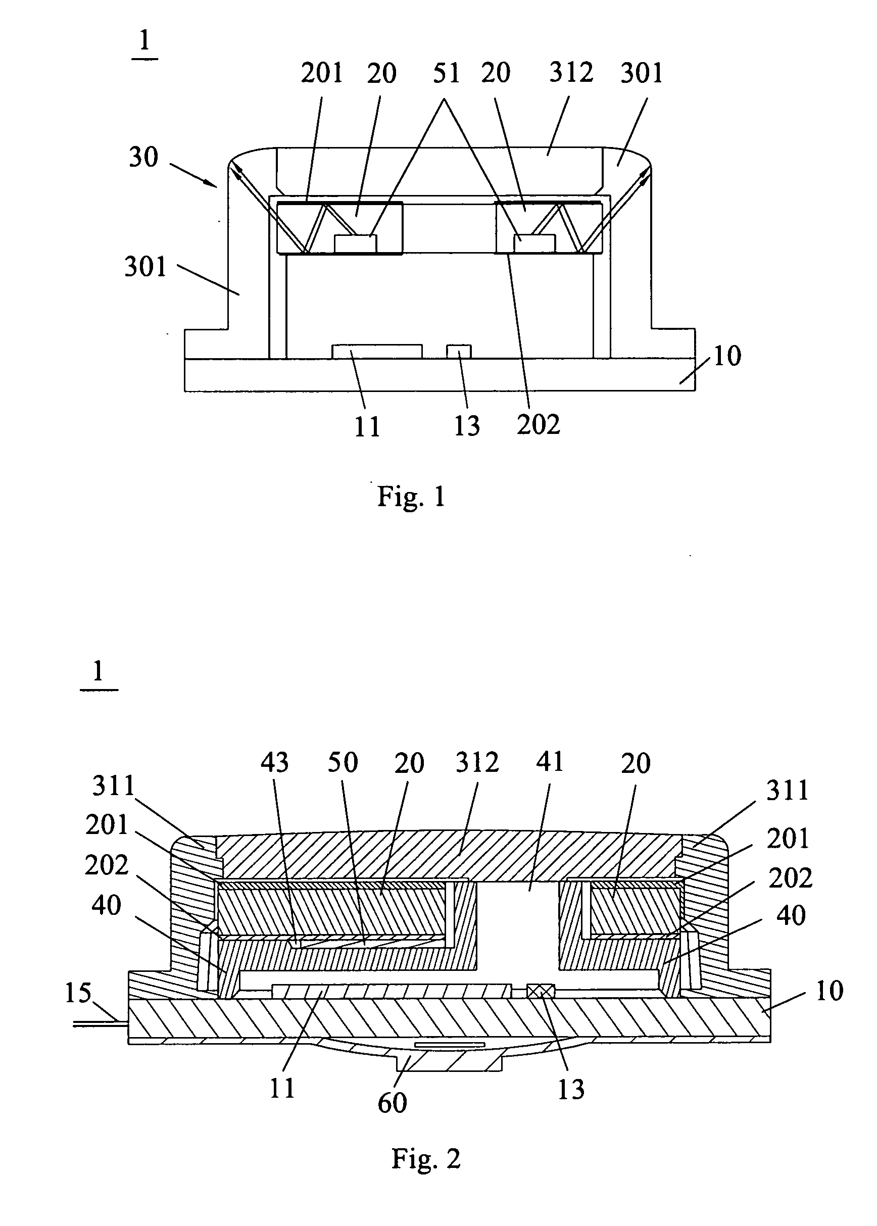
[0006]One aspect of the present invention is to realize an optical navigation apparatus with a part of its outer housing uniformly illuminated to form a clearly illuminated character shape on the outer housing to enhance the cosmetic effect and allow the navigation apparatus to be recognized and used under low-light environment.
[0022]In comparison with the prior art, the optical navigation apparatus of the present invention has not only a light guide for guiding the visible light to the rim of the outer housing, but also an outer housing that is multi-function. The outer housing of the present invention is not only used as a protective casing to facilitate infrared signal propagation, but also served as a secondary light-guiding and distribution structure to reflect and re-distribute visible light sufficiently to achieve a uniform illuminated character shape. The visible light coupled into the side wall of the housing can be sufficiently scattered, and the light distribution can be uniform and even to reach the ring of the outer housing for illumination.

Problems solved by technology

With the previous apparatus design, it is not possible to achieve this illumination effect as visible light is blocked from transmission through the outer housing walls.

Method used


Image

  • Optical navigation apparatus
  • Optical navigation apparatus
  • Optical navigation apparatus

Examples


Embodiment Construction

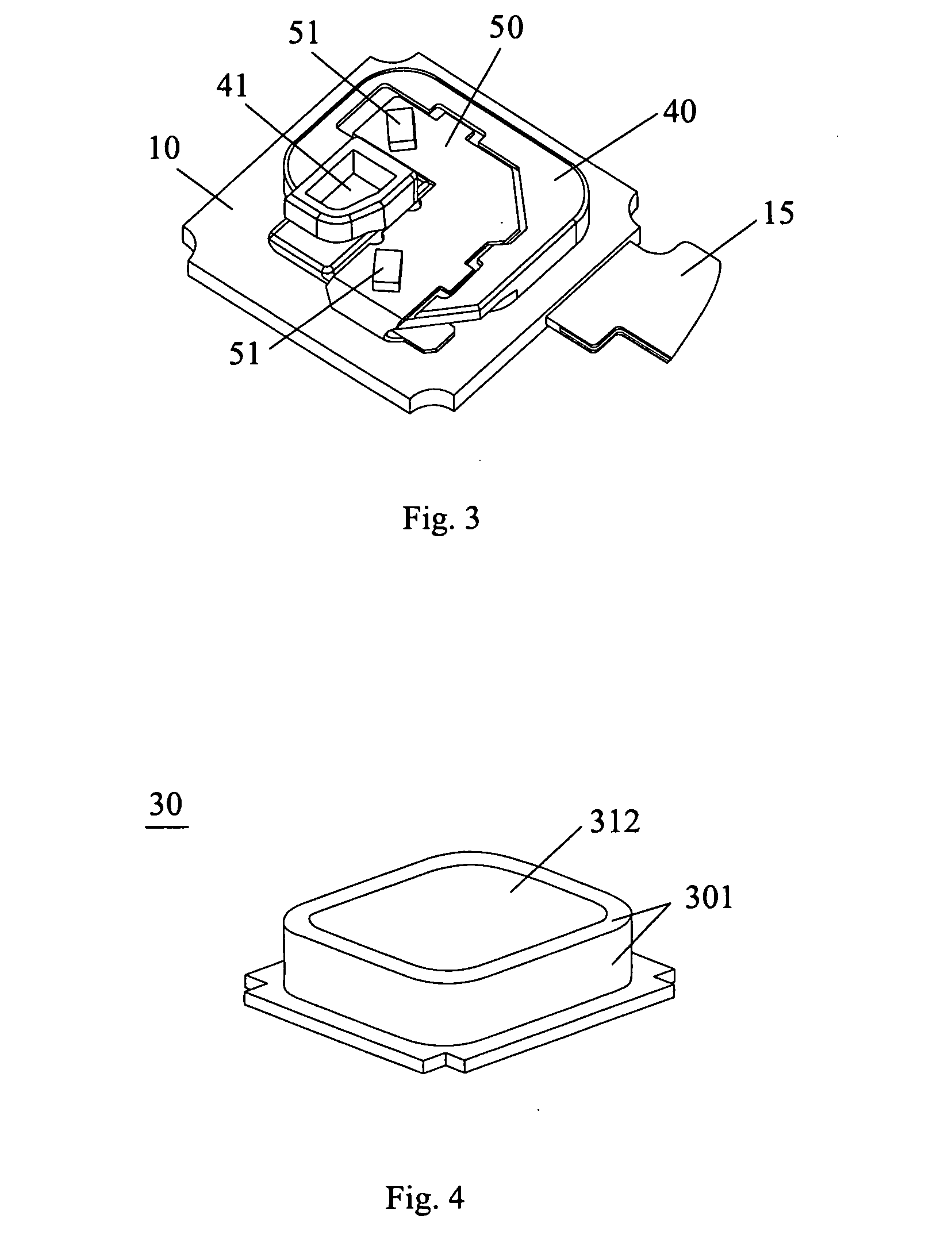
[0033]Various preferred embodiments of the invention will now be described with reference to the figures, wherein like reference numerals designate similar parts throughout the various views. The invention is directed to an optical navigation apparatus used in finger motion recognition system, as an instruction input port, wherein the apparatus is capable of generating internal illumination using a plurality of internal visible light source, an internal light-guiding element and an outer housing with a side wall capable of guiding visible light and light-reflecting coating outside the side wall. In such an arrangement, the outer housing of the present invention is not only used as a casing for protection, but also served as a light guiding structure to reflect and re-distribute visible light sufficiently. The visible light generated by the internal visible light source can be scattered adequately via here, and the light distribution can be uniform and even to reach the ring of the o...


PUM


Abstract

An optical navigation apparatus comprises a substrate with a sensor integrated circuit and an infrared source formed thereon; a sensor cover shielding the sensor integrated circuit and the infrared source; at least one visible light source formed outside the sensor cover and electrically connected with the substrate; a light guide located outside the sensor cover and covering the visible light source; and an outer housing covering the light guide and the substrate, and the outer housing comprises an infrared window and a side wall capable of guiding visible light towards and illuminating a region of the outer housing. In such an arrangement, the outer housing of the present invention is not only used as a casing for protection, but also served as light guide and distribution structure to reflect and re-distribute light sufficiently to achieve a uniform illuminated character shape.

Description

FIELD OF THE INVENTION[0001]The present invention relates to an optical navigation apparatus, and more particularly, to an optical navigation apparatus with an outer housing that can be illuminate with internal light source.BACKGROUND OF THE INVENTION[0002]Optical navigation apparatus are used in portable electronic appliances as a user input device for graphic user interface (GUI) control. Optical navigation apparatus operates by registering relative movement between the optical navigation apparatus and a target sensing surface in close proximity to the sensing area of the apparatus and convert the movement information into electronic format accessible by external system. An optical navigation apparatus uses a light source, such as a light emitting diode (LED) or laser to illuminate user's finger and a sensor to capture reflected light off the target surface. The control logic within the optical navigation apparatus compares consecutive changes in reflected light pattern and estima...

Claims


Application Information

Patent Timeline
Patent Type & Authority Applications(United States)
IPC IPC(8): G06F3/033H01J40/14
CPCG06F3/042G06F3/03547
Inventor HUNG, WAIGAMBOA, FRANCIS GUILLENYU, XIAOMING
Owner CLOUD LIGHT TECH LTD
Learn More