
Numerical Model For Simulating Polymeric Material Properties

a numerical simulation and polymer material technology, applied in the field of computer-aided mechanical engineering analysis, can solve the problems of inability to fully describe all the unique properties of polymeric materials, inability to perform numerical simulations, and inability to accurately simulate polymeric materials

Inactive Publication Date: 2011-11-24
LIVERMORE SOFTWARE TECH
View PDF0 Cites 4 Cited by
  • Summary
  • Abstract
  • Description
  • Claims
  • Application Information

AI Technical Summary

Benefits of technology

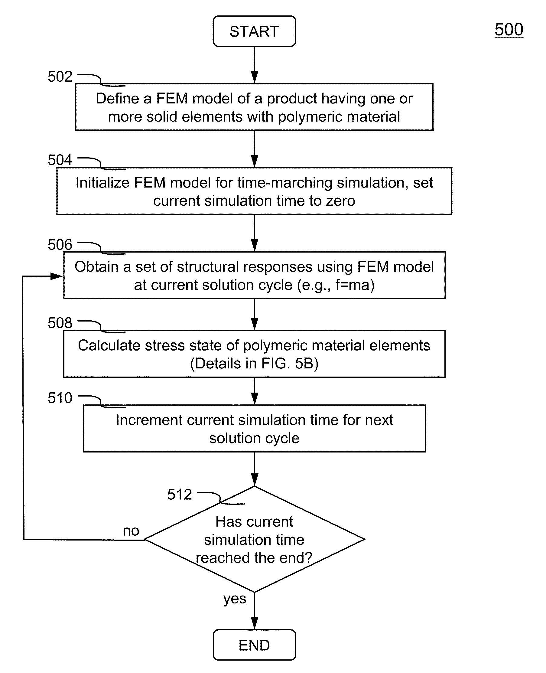
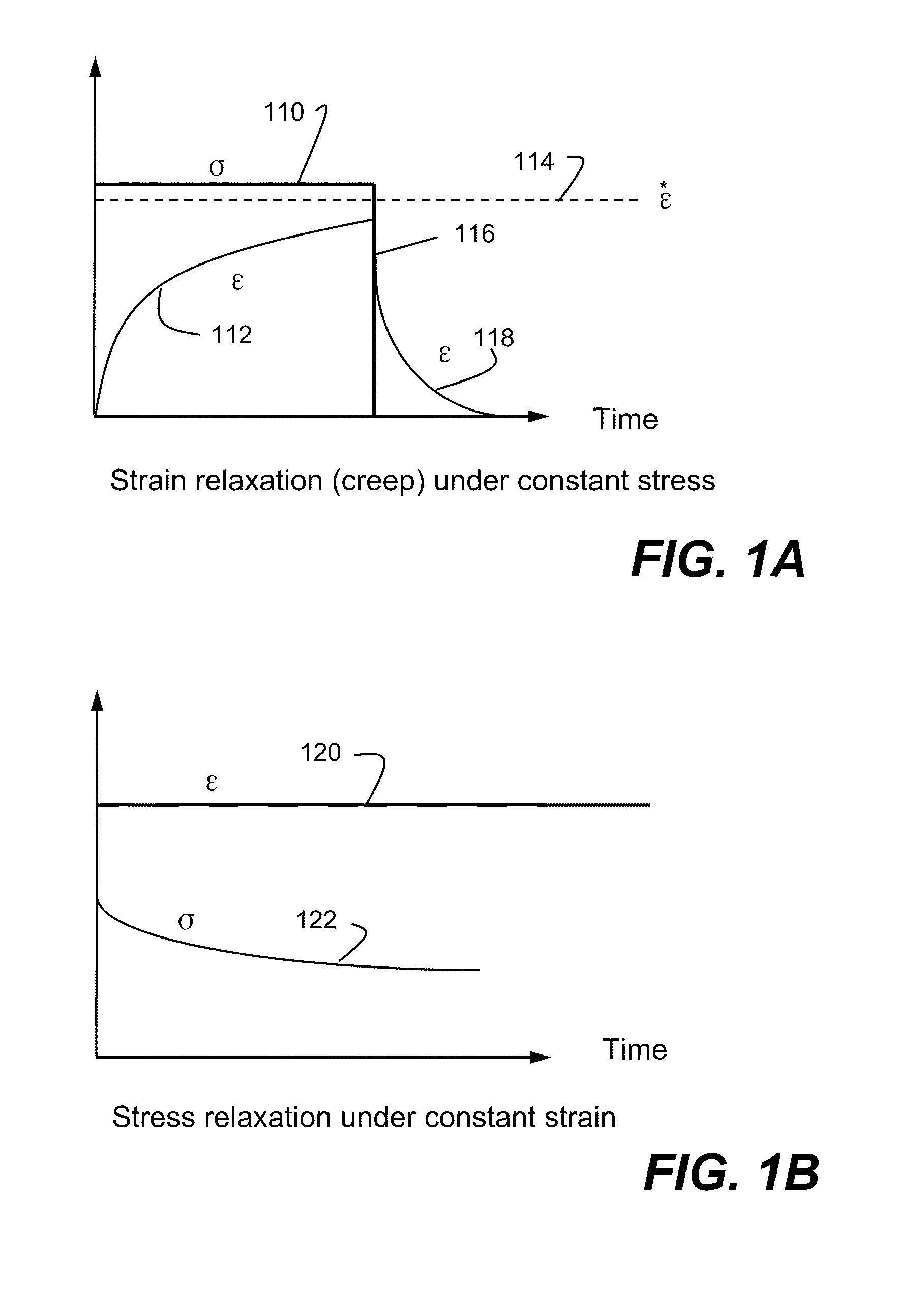
The present invention is about methods and systems for using a numerical model to describe the properties of polymeric materials in a computational environment. The model takes into account all characteristics of the material, including the Mullins effect and strain hardening effect, as well as elastic stress, viscoelastic stress, and back stress. The model is used to calculate the stress state of the material under loads and to determine whether the elements are under plastic deformation. The results of the polymeric material elements are obtained when the updated stress state is within a tolerance of the yield surface. Overall, the invention provides a more accurate and reliable way to analyze the properties of polymeric materials in a computational environment.

Problems solved by technology

The patent text discusses the use of polymeric materials in products and the difficulty in predicting their response to mechanical loads due to their long chain structure. The technical problem addressed in the text is the lack of a material model that can accurately predict the response of polymeric materials under large nonlinear deformations.

Method used


Image

  • Numerical Model For Simulating Polymeric Material Properties
  • Numerical Model For Simulating Polymeric Material Properties
  • Numerical Model For Simulating Polymeric Material Properties

Examples


Embodiment Construction

[0015]In the following description, numerous specific details are set forth in order to provide a thorough understanding of the present invention. However, it will become obvious to those skilled in the art that the present invention may be practiced without these specific details. The descriptions and representations herein are the common means used by those experienced or skilled in the art to most effectively convey the substance of their work to others skilled in the art. In other instances, well-known methods, procedures, components, and circuitry have not been described in detail to avoid unnecessarily obscuring aspects of the present invention.

[0016]Reference herein to “one embodiment” or “an embodiment” means that a particular feature, structure, or characteristic described in connection with the embodiment can be included in at least one embodiment of the invention. The appearances of the phrase “in one embodiment” in various places in the specification are not necessarily ...


PUM


Abstract

Methods and systems using a numerical model to describe polymeric material properties are disclosed. FEM model of a product is defined. FEM model includes one or more solid elements of polymeric material. In a time-marching simulation of the product under loads, stress state of the solid elements is calculated from deformation gradient tensors. Stress state incorporates the Mullins effect and strain hardening effect, also includes elastic stress, viscoelastic stress and back stress. A yield surface is defined to determine whether the elements are under plastic deformation. Plastic strain is obtained to update the deformation gradient tensor, which is then used to recalculate the stress state. Calculations continue until updated stress state is within a tolerance of the yield surface, at which time the results of polymeric material elements are obtained. The numerical model takes into account all characteristics of a polymeric material.

Description


Claims


Application Information

Patent Timeline
Owner LIVERMORE SOFTWARE TECH
Learn More