
Method of receiving charge, method of controlling charge, charge control unit and charging equipment

a technology of charging control unit and charging equipment, applied in the direction of charging station, electric vehicle charging technology, transportation and packaging, etc., can solve the problems of users not knowing when the vehicle during charging completes the charging, needs a long time to charge the battery, and significant inconvenien

Active Publication Date: 2011-11-24
HITACHI LTD
View PDF15 Cites 79 Cited by
  • Summary
  • Abstract
  • Description
  • Claims
  • Application Information

AI Technical Summary

Benefits of technology

[0012]By using the above mentioned construction, when the device mounted with battery is connected with the user operation unit in the charge equipment, the charge control unit distributes the available electric power at that time to the user operation unit as a power source, to supply the distributed electric power to the user operation unit so as to charge the battery of the device mounted with battery. Then, every time when the device mounted with battery is connected with the user operation unit, the available electric power at that time is allocated to the user operation unit, allowing the battery to be charged. Accordingly, by using the single charging equipment, the plurality of user operation units can be charged, allowing the plurality of devices mounted with battery can be charged simultaneously.
[0016]By using the above mentioned construction, the plurality of user operation units can be used for charging batteries by the single charging equipment. Accordingly, by using the plurality of the user operation units in the charging equipment capable of simultaneously charging a plurality of the devices mounted with battery, a user can easily request a timer charge or a quick charge through an acceptance screen having a timer charge acceptance part and a quick charge acceptance part displayed on a display part.
[0020]By using the above mentioned construction, when another device mounted with battery is to be charged during the device mounted with battery is being charged, it is possible to charge another device mounted with battery without influencing the operation performance of the device mounted with battery which is being charged.
[0024]By using the above mentioned construction, when a plurality of devices mounted with battery are simultaneously charged, if one power conversion unit completes the charging for a device mounted with battery, it is possible to allocate the power conversion unit to the other device mounted with battery. Accordingly, it is possible to more efficiently use the power conversion unit, resulting in the increase of the charging efficiency.
[0028]By using the above mentioned construction, the charge pattern can be set manually, which allows the battery to be charged associated with the charge pattern corresponding to the request by the user. Hereby, it is possible to provide a flexible service corresponding to a request from a user.
[0031]According to the present invention, it is possible to simultaneously charge the plurality of devices mounted with battery by using the single charging equipment.

Problems solved by technology

Although a technology for quick charging has been developed, under the present circumstances, it needs a long time to charge a battery.
Hereby, when a vehicle occupies a charging station, other users have to wait their turn, resulting in causing the significant inconvenience.
Therefore, users can not know when the vehicle during charging completes the charging, which is a factor for spoiling the convenience of the users.
However, this is not realistic because the costs required for preparing the charge converter devices 82 increase.

Method used


Image

  • Method of receiving charge, method of controlling charge, charge control unit and charging equipment
  • Method of receiving charge, method of controlling charge, charge control unit and charging equipment
  • Method of receiving charge, method of controlling charge, charge control unit and charging equipment

Examples


first embodiment

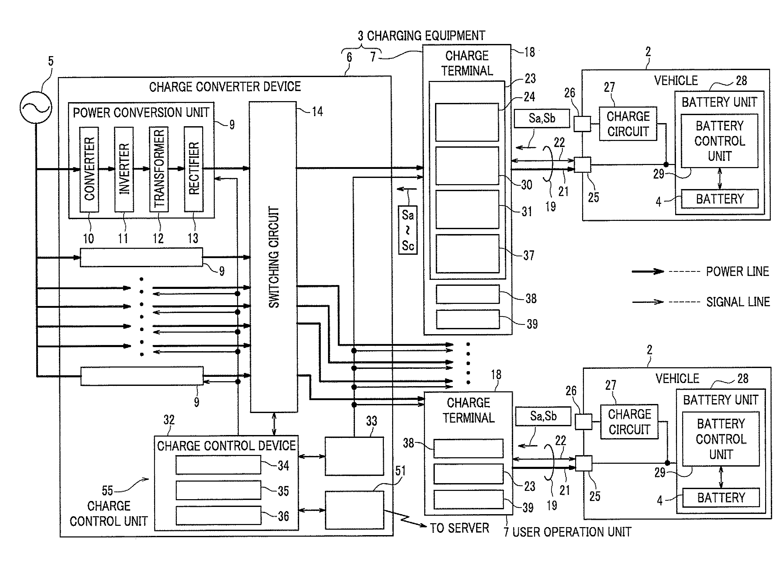
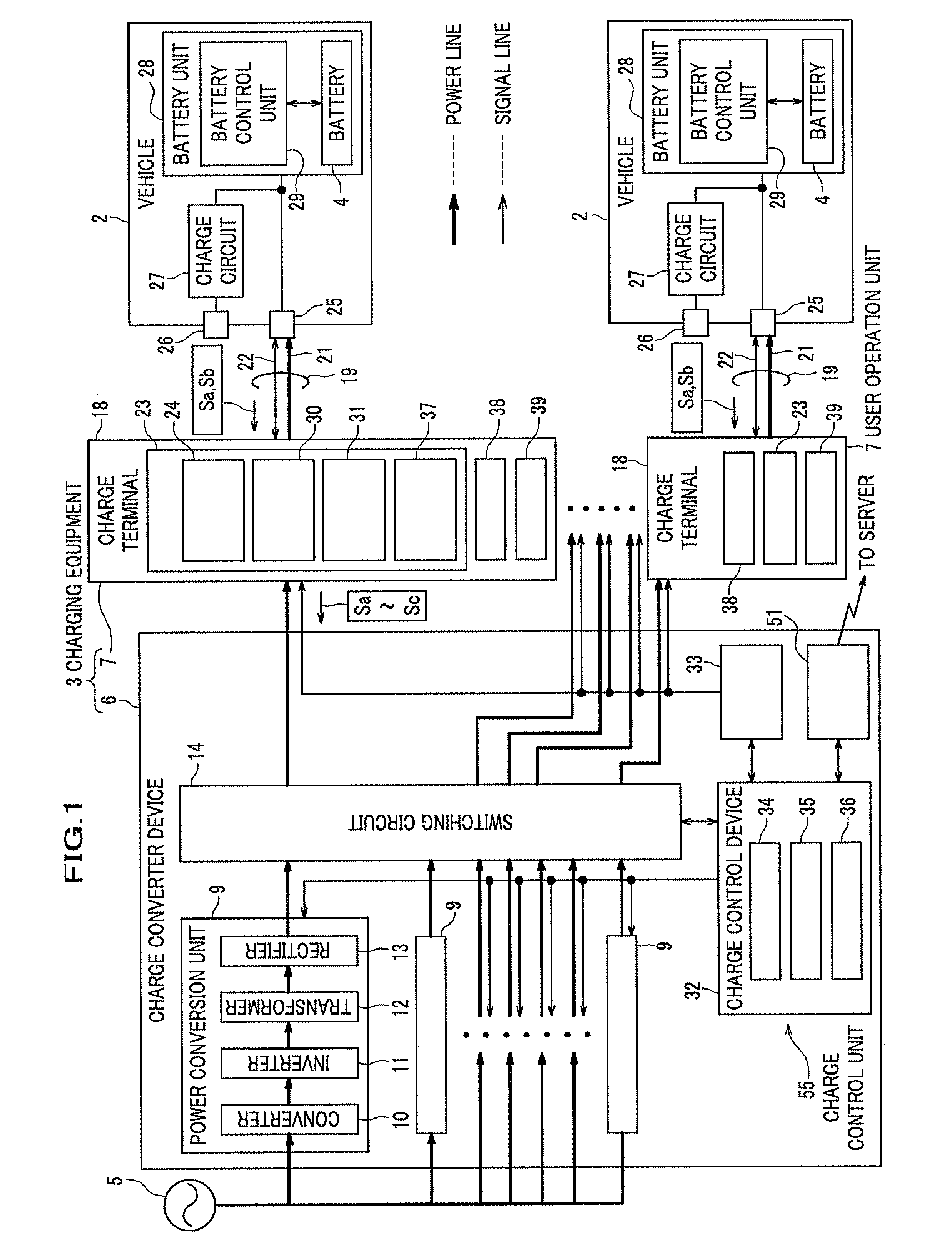
[0062]Next, a first embodiment of the present invention will be explained in reference to the attached drawings of FIGS. 1 to 6.

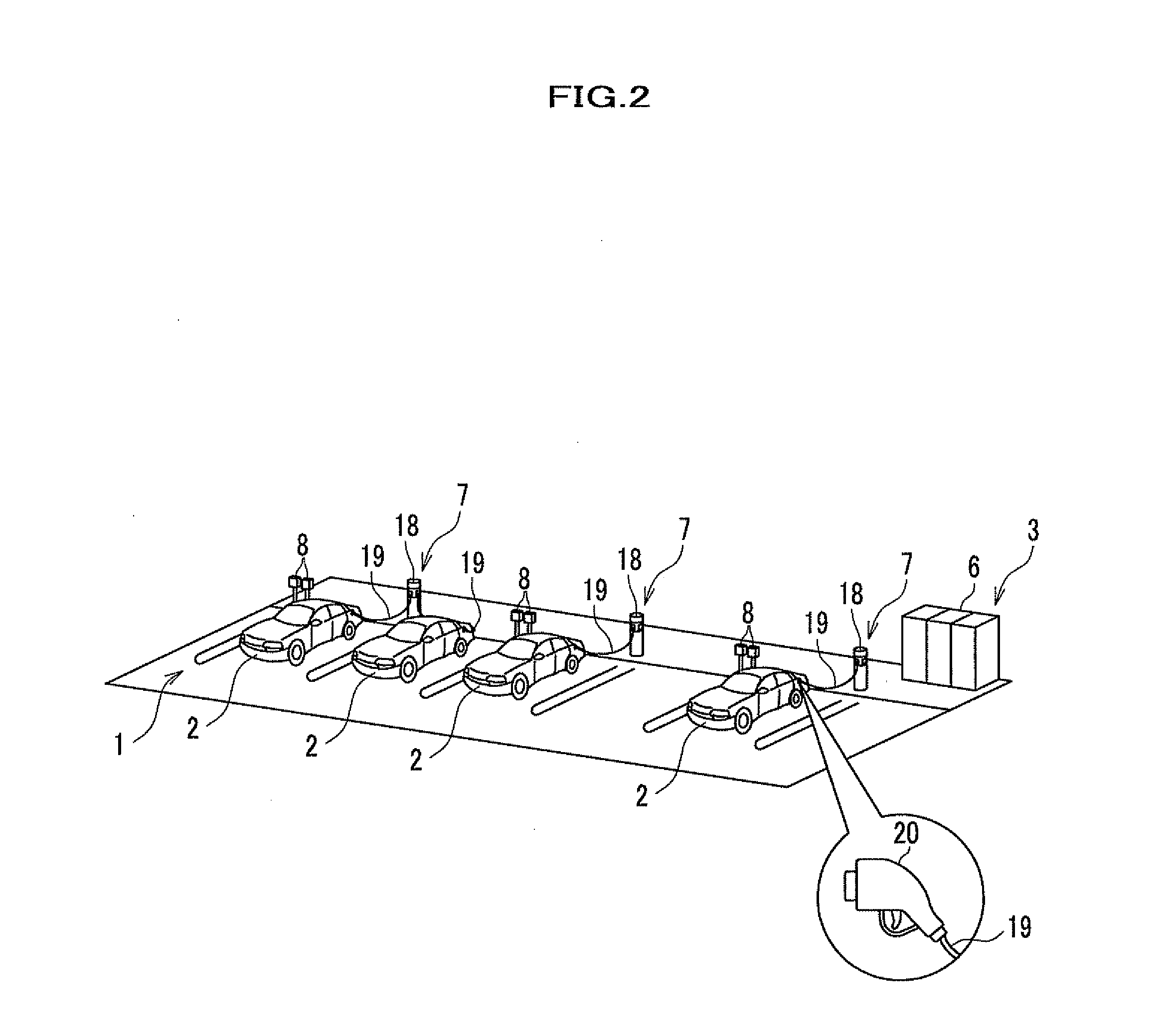
[0063]As shown in FIG. 2, in a parking lot 1, charging equipment 3 (or charging station) is placed, which can charge a parking electric automobile or a hybrid vehicle (hereinafter, referred to vehicle 2). The charging equipment 3 of the present embodiment is high speed charging equipment which supplies a high DC voltage such as DC 500V to the vehicle 2 for charging a battery 4 (see FIG. 1) of the vehicle 2 in a short time. Herein, the vehicle 2 corresponds to a device mounted with battery.

[0064]The charging equipment 3 comprises a charge converter device 6 which converts an AC power voltage obtained from a system power supply 5 such as a commercial power source to a DC power voltage and outputs the converted voltage for charging, and a user operation unit 7 which is connected with the vehicle 2 by a user when charging. In the parking lot 1, a parking mater ...

second embodiment

[0120]Next, a second embodiment of the charging equipment of the present invention will be described. Herein, for the common parts with the first embodiment, the constructions and descriptions shown in the first embodiment can be applied thereto. Therefore, the different parts from the first embodiment will be mainly explained.

[0121]In the first embodiment, in the charging equipment 3, the manually setting function is provided for manually setting the charge pattern of the battery 4 at the charge terminal 18. When the charge pattern is set, the charge operation is conducted following the set charge pattern. In the second embodiment, by using the manually setting function, a function of the timer charge is more specifically realized, by which the charge operation is conducted to satisfy the charge schedule defining the charge end time of the battery 4 equipped with a vehicle 102 as a device mounted with battery. Further, a function of the quick charge is more specifically realized, b...


PUM


Abstract

Charging equipment and a charge control unit are provided, in which a plurality of devices mounted with battery can be simultaneously charged by the single charging equipment. Further, a method of controlling charge and a method of receiving charge are also provided. The charging equipment supplies electric power to the battery for charging, comprising a power output part which outputs DC power used for charging, a plurality of user operation units which can be connected with a vehicle equipped with a battery as a device mounted with battery, and the charge control unit which controls a power supply from the power output part to the user operation unit. Herein, the charge control unit distributes the electric power outputted from the power output part to supply the distributed power to the user operation unit connected with the vehicle.

Description

CROSS REFERENCE TO RELATED APPLICATIONS[0001]This application claims the foreign priority benefit under Title 35, United State Code, 119 (a)-(d) of Japanese Patent Application No. 2010-115420, filed on May 19, 2010 and No. 2011-084682, filed on Apr. 6, 2011 in the Japan Patent Office, the disclosure of which is herein incorporated by reference in its entirety.BACKGROUND OF THE INVENTION[0002]1. Field of the Invention[0003]The present invention relates to a method of receiving charge, a method of controlling charge, a charge control unit and charging equipment, for charging a battery in a device mounted with battery such as an electric automobile.[0004]2. Description of Related Art[0005]Recently, because of an increasing concern about environmental aspects, an electric automobile and a hybrid vehicle have been widely used as a vehicle discharging less exhaust gas. Such a vehicle is equipped with a battery which supplies an electric power to a motor so that the vehicle runs by the mot...

Claims


Application Information

Patent Timeline
IPC IPC(8): H02J7/04H02J7/00H02J7/02
CPCY02T10/7005B60L11/1824B60L11/1825B60L11/1838B60L11/1844B60L11/185Y02T90/121H02J7/045Y02T90/14Y02T90/128Y04S10/126Y02E60/721H02J7/0027Y02T10/7072B60L53/20B60L53/31B60L53/63B60L53/11B60L53/67H02J2310/48B60L53/62B60L53/66B60L53/305Y02E60/00Y02T10/70Y02T90/12Y02T90/16H02J7/04H02J7/0013H02J7/007182H02J7/0042
Inventor KAWAI, SHOJIMARUI, TOMOYUKITAKAHASHI, MASAMIRISSEN, KAZUMIEBARA, TAKAFUMIYONEZAWA, KEINASU, YOSHIHITO
Owner HITACHI LTD
Learn More