
Refrigerator

a technology of refrigerators and cooling fluids, applied in the field of refrigerators, to achieve the effect of high energy efficiency

Inactive Publication Date: 2011-11-24
BSH BOSCH & SIEMENS HAUSGERAETE GMBH
View PDF13 Cites 1 Cited by
  • Summary
  • Abstract
  • Description
  • Claims
  • Application Information

AI Technical Summary

Benefits of technology

[0005]In view of these factors, an object of the invention is to solve at least one of the technical problems found in the prior art so that the temperature of the dispenser casing may be evenly increased with a higher energy efficiency to prevent the dispenser casing from forming condensation and / or to remove any condensed water from the dispenser casing.
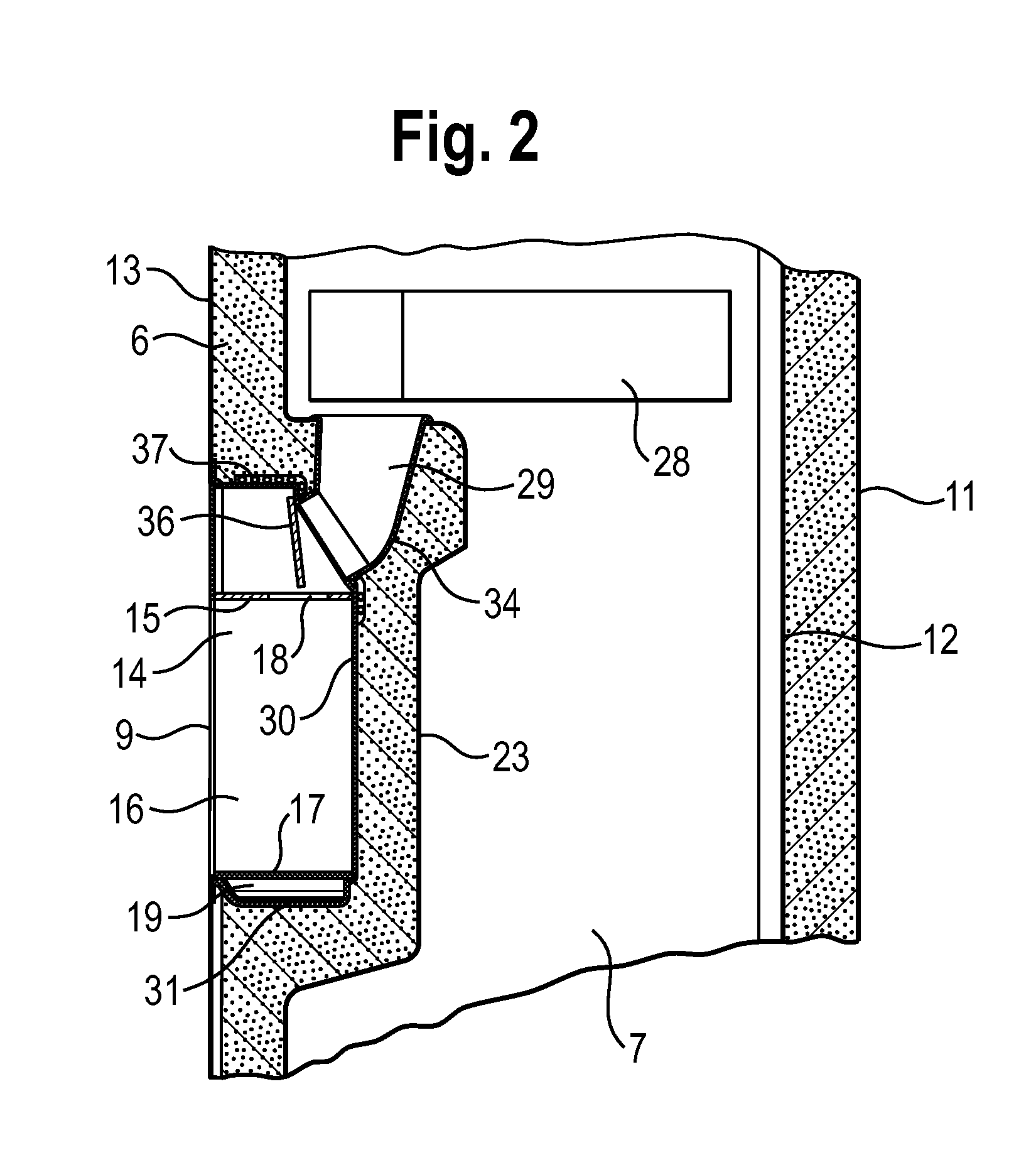
[0007]In this way, the heat generated by the heater can be transmitted to the dispenser casing rapidly and evenly. On one hand, this configuration can prevent the portions of the dispenser casing which are adjacent to the heater from being overheated and the portions of the dispenser casing which are distant from the heater from being under heated and thus generating condensate, so that it is expected that condensation on the dispenser casing can be avoided with a reasonable energy consumption. On the other hand, by means of the heat transmitting function of the heat conducting element, the reaching area of the heat generated by the heater can be enlarged by the heat conducting element. That is to say, the heat generated by the heater may form a heat source for the heat conducting element and will be transmitted quickly by the heat conducting element, so that the deploying area of the heater can be advantageously reduced. For example, only the portions of the dispenser casing which are likely to occur condensation may be provided with a heater while other portions of the dispenser casing which are not likely to occur condensation may be only covered and supplied with heat by the heat conducting element.
[0010]According to a preferred embodiment of the invention, the dispenser casing defines a dispensing cavity for receiving at least a part of an outside container, the dispensing cavity comprises a dispensing cavity wall extending in a longitudinal direction, and the heat conducting element covers at least a major portion of the dispensing cavity wall. Thus, the dispensing cavity wall may be evenly heated to reduce the possibility of occurring condensation. In addition, the dispensing cavity wall may be touched by a user. For this end, the heat conducting element is provided for preventing the dispensing cavity wall from being overheated, and thus any potential harm to the user by the overheated dispensing cavity wall can be avoided.
[0015]According to a preferred embodiment of the invention, the heater is arranged adjacent to the ice transfer passage. In this way, the portions of the dispenser casing which are located near the ice transfer passage will obtain more heat, so that the condensation possibility can be reduced. In addition, in the condition that the ice transfer passage is blocked by a closure element which closes a through hole, the condition that the closure element is frozen and thus cannot be opened can be advantageously avoided by means of the first heater provided adjacent to the ice transfer passage.
[0016]Although it is possible to arrange the heater adjacent to the dispenser casing but not directly contact with the dispenser casing, it is preferably that the heater is connected to the dispenser casing according to a preferred embodiment of the invention, so that the heat generated by the heater may be transmitted quickly to the dispenser casing, and thus the influence of the heat generated by the heater to the storage space is reduced.
[0017]According to a preferred embodiment of the invention, the heater comprises a first heater and a second heater which are controlled independently from each other. According to a preferred embodiment of the invention, the dispenser casing comprises a first area and a second area located near the first area, the first area and the second area are arranged adjacent to the heat insulating layer, and the first and second heater are disposed in the first area and the second area respectively. Thus, condensation can be prevented more effectively. For example, different heaters may be properly disposed according to the condensation characteristics of different areas of the dispenser casing, and it may prevent the occurring of condensation or removing the generated condensate more efficiently by individually control these heaters.

Problems solved by technology

Thus, in a dew prevention / dew removing process, some areas of the door may be overheated while other areas may be of a temperature that is too low to prevent dewing.

Method used


Image

  • Refrigerator
  • Refrigerator
  • Refrigerator

Examples


Embodiment Construction

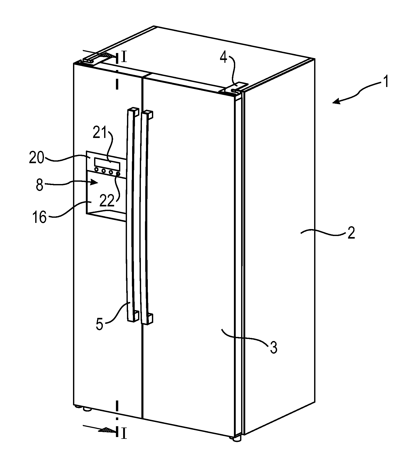
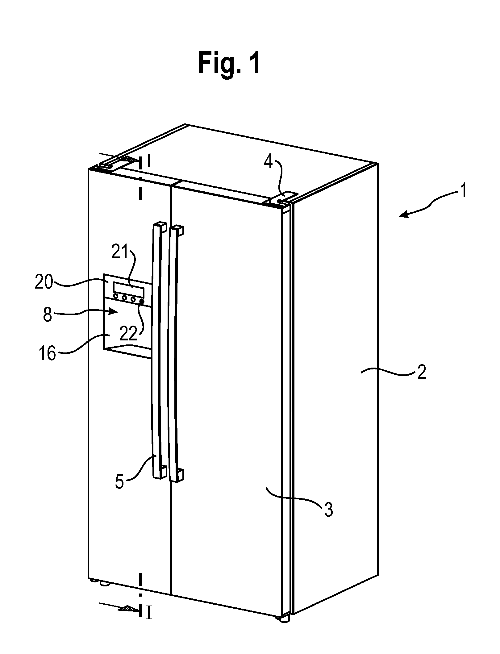
[0025]Please refer to the drawings, in particular FIGS. 1 and 2. A refrigerator 1 comprises a refrigerator body 2 and two doors 3 connected to the refrigerator body 2, as shown in FIGS. 1 and 2.

[0026]The refrigerator body 2 comprises an outer shell 11, an inner shell 12 and a heat insulating layer 6 disposed between the outer shell 11 and the inner shell 12. In this embodiment, the heat insulating layer 6 is a foam-based insulating layer and is formed by foaming a heat insulating foam material.

[0027]The refrigerator body 2 defines at least one storage space for storing food. In this embodiment, the storage space comprises a freezing compartment 7 and a refrigerating compartment (not shown) which are juxtaposed with each other.

[0028]The doors 3 are pivotably connected to the refrigerator body 2 by hinges 4 respectively, and are rotatable about their corresponding rotation axes which are parallel to a vertical axis. As shown in FIG. 2, it is also provided with a foam-based insulating ...


PUM


Abstract

A refrigerator includes a refrigerator body defining at least one storage space and a door connected to the refrigerator body for closing at least a part of the storage space. The door includes a heat insulating layer. A dispenser is provided in the door and has a dispenser casing which is adjacent to the heat insulating layer. A heater is arranged at least adjacent to the inner side of the dispenser casing and a heat conducting element covers at least a part of the inner surface of the dispenser casing in facing relationship to the heat insulating layer. The heat conducting element is arranged at least adjacent to the heater for transmitting the heat generated by the heater to the dispenser casing.

Description

TECHNICAL FIELD[0001]The invention relates to a refrigerator, especially to a household or commercial refrigerator which is provided with a dispenser.BACKGROUND ART[0002]The freezing compartment of a refrigerator can usually reach a temperature of lower than minus ten ° C. or more. The refrigerator body and the door of the refrigerator are provided with heat insulating layers to avoid losing of cold energy caused by heat exchange between the cold air within the refrigerator and the surrounding environment. However, as the increase in the refrigerator's volume and in the number of the components of the refrigerator door (for example, a dispenser for dispensing water or ice), some portions of the refrigerator door which are exposed to the atmosphere may have relatively low temperature under the influence of the storage compartment. When the difference between the temperature of the surface exposed to the atmosphere and the atmosphere temperature reaches dew point temperature, condensa...

Claims


Application Information

Patent Timeline
IPC IPC(8): F25D21/00
CPCF25C5/005F25C2400/10F25D21/04F25D2400/361F25D23/126F25D2400/06F25D21/08F25C5/22
Inventor BAI, YUFAGAO, LIANGLU, SONGTAOZHU, QIWU
Owner BSH BOSCH & SIEMENS HAUSGERAETE GMBH
Learn More