Heater supporting device

a technology of supporting device and heating element, which is applied in the direction of heat production device, electrical apparatus, stand/trestle, etc., can solve the problems of heat leakage through the gap, short circuit between different parts of the heating element, and accidental electrical leakage, so as to increase the uniformity of temperature property and the expected lifespan, and prevent adiabatic efficiency deterioration

Active Publication Date: 2011-11-17
KOKUSA ELECTRIC CO LTD
View PDF5 Cites 2 Cited by
  • Summary
  • Abstract
  • Description
  • Claims
  • Application Information

AI Technical Summary

Benefits of technology

[0018]The present disclosure in some embodiments provides a heater supporting device for use in a semiconductor manufacturing apparatus, which may prevent support pieces from being damaged and separated from piece holders and prevent a deterioration in adiabatic efficiency in the vicinity of a ceiling portion, thereby increasing the uniformity of temperature property and the expected lifespan.

Problems solved by technology

This in turn may cause a short circuit between different portions of the heating element 13 due to an electrical coupling thereof.
Also, the heating element 13 may contact the uniform heat tube 3, which may cause an accident such as electric leakage.
As a result, a gap may be formed between the ceiling heat insulator 17 and the periphery heat insulator 16, which causes heat leakage through the gap and deteriorates the adiabatic efficiency.

Method used


Image

  • Heater supporting device
  • Heater supporting device
  • Heater supporting device

Examples


first additional embodiment

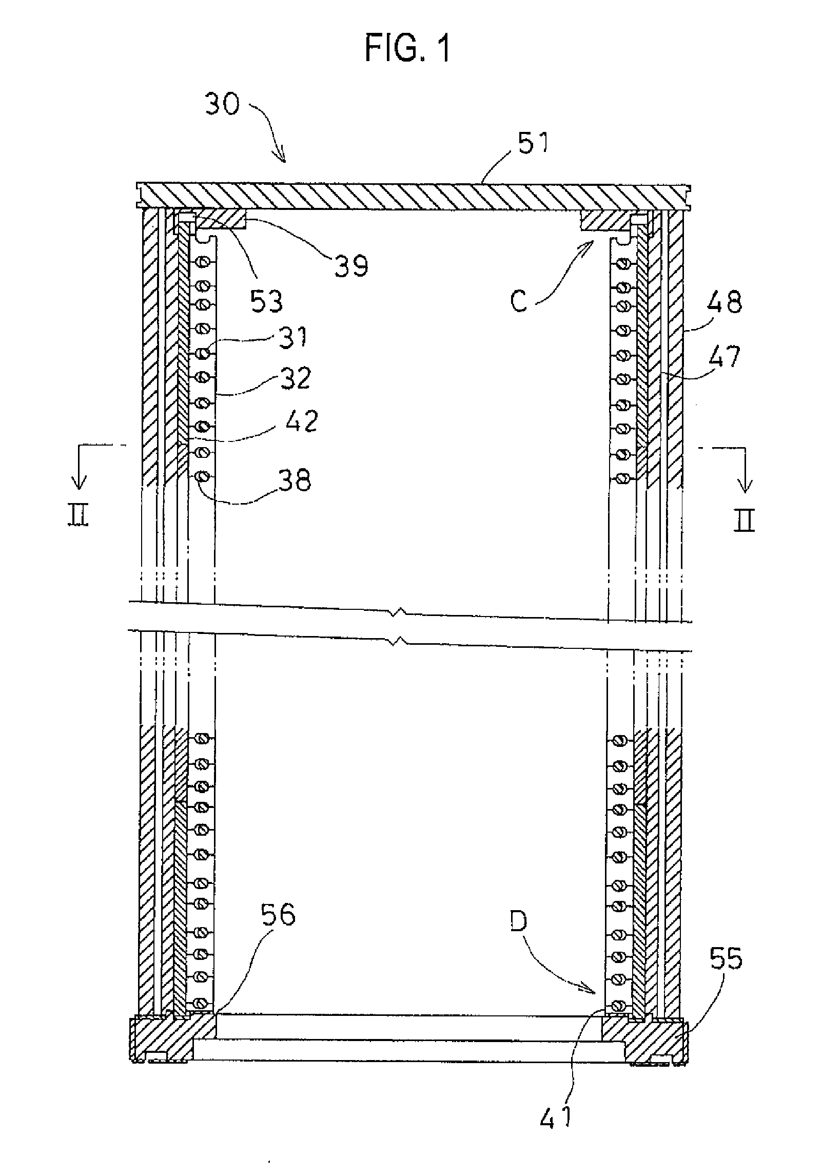
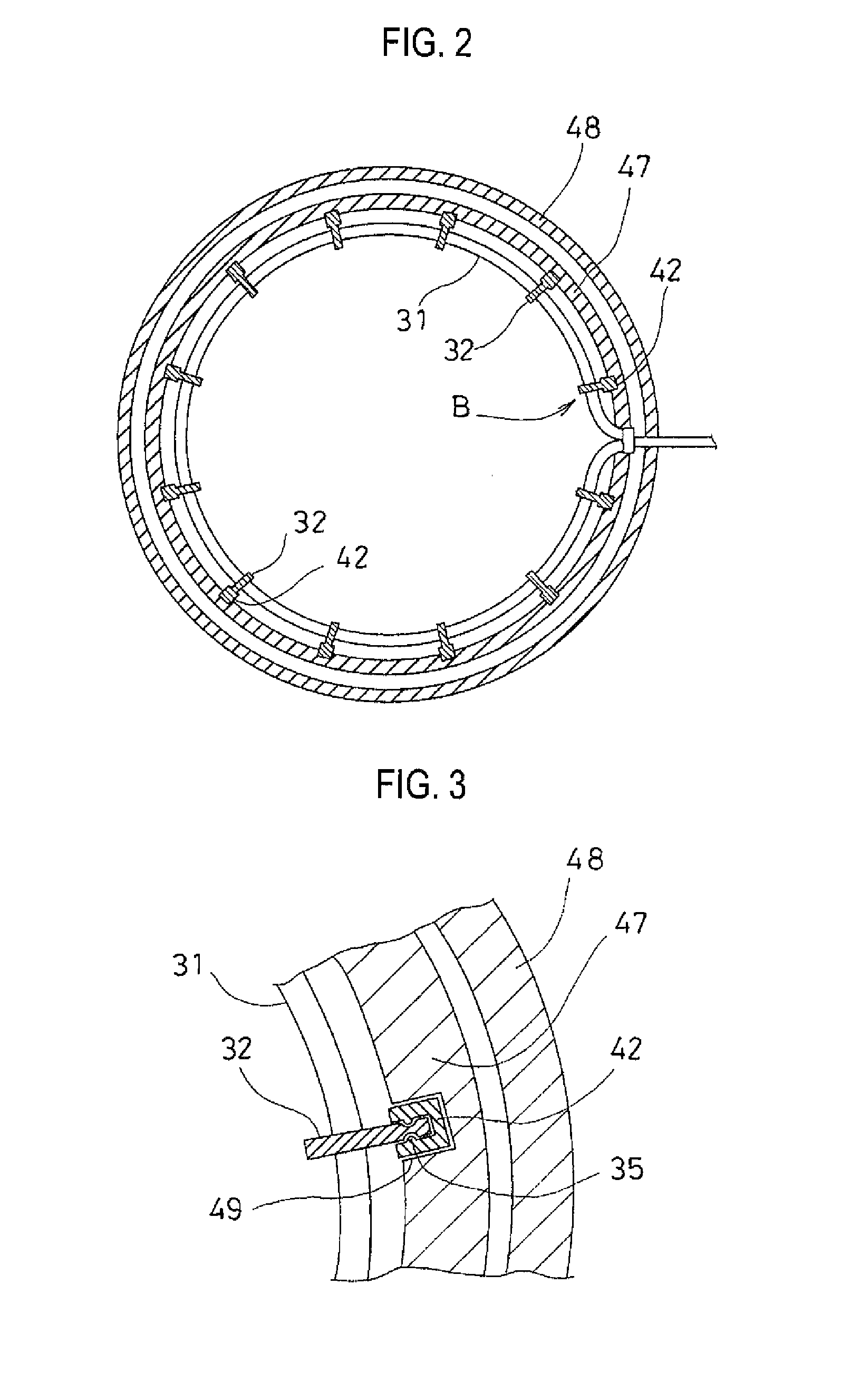
[0070]According to a first additional embodiment of the present disclosure, there is provided a heater supporting device including: a heating element having a coil shape and being disposed around an object to be heated; support pieces being vertically connected in multiple; and hollows having an elliptical shape elongated in a radial direction and being formed between the support pieces connected to each other, wherein the heating element is inserted into the hollows and supported by the support pieces. A concave insertion is formed, in a direction intersecting with the heating element, on one of upper and lower portions of each of the support pieces and a convex insertion is formed on the other one of the upper and lower portions of the respective support pieces, the convex insertion being insert-fitted to the concave insertion. The support pieces are vertically connected to each other by insert-fitting the convex insertion to the concave insertion.

second additional embodiment

[0071]In the heater supporting device according to the first additional embodiment, the support pieces are supported by a plurality of piece holders being vertically provided to control the movement of the support pieces in a horizontal direction. Further, the piece holders are supported by a periphery heat insulator disposed around the heating element.

third additional embodiment

[0072]In the heater supporting device according to the first additional embodiment, the concave insertion and the convex insertion are formed in a radial direction with respect to the object to be heated, extending from one end of the upper and lower surfaces of the respective support pieces to the other end thereof.


PUM


Abstract

A heater supporting device for use in a semiconductor manufacturing apparatus is provided so as to improve the uniformity of a temperature property and the expected lifespan by preventing support pieces from being damaged and separated from piece holders, and preventing deterioration in adiabatic efficiency in the vicinity of a ceiling of a vertical type furnace. A heating element of a coil shape is disposed around an object. The support pieces are vertically connected in multiple. Hollows of an elliptical shape are formed between the respective support pieces. Concave insertions are formed on one of upper and lower surfaces of the respective support pieces, and convex insertions are formed on the other one of the upper and lower surfaces of the respective support pieces. The convex insertions are insert-fitted with the concave insertions. The support pieces are vertically connected in multiple by insert-fitting the concave insertions to the convex insertions.

Description

CROSS-REFERENCE TO RELATED APPLICATIONS[0001]This application is based upon and claims the benefit of Japanese Patent Application No. 2010-108968, filed on May 11, 2010, and Japanese Patent Application No. 2011-58673, filed on Mar. 17, 2011, the entire contents of which are hereby incorporated by reference.TECHNICAL FIELD[0002]Embodiments described herein relate to a heater supporting device used in a semiconductor manufacturing apparatus, and more particularly, in a vertical type furnace employed in a semiconductor manufacturing apparatus.BACKGROUND[0003]A vertical type furnace may be employed to perform a semiconductor manufacturing process such as a diffusion process and a chemical vapor deposition (CVD) process.[0004]The vertical type furnace heats up an interior thereof and supplies a reaction gas thereto, to thereby form a thin film on a surface of a substrate to be processed such as a wafer or the like. The vertical type furnace is provided with a heater for this purpose.[000...

Claims


Application Information

Patent Timeline
Patent Type & Authority Applications(United States)
IPC IPC(8): F16M11/00
CPCH01L21/67109
Inventor KOSUGI, TETSUYAMURATA, HITOSHISUGIURA, SHINOBUUENO, MASAAKI
Owner KOKUSA ELECTRIC CO LTD
Why Eureka
Try Eureka