Ripple Cancellation
a power conversion system and ripple technology, applied in the direction of electric variable regulation, process and machine control, instruments, etc., can solve the problems of inefficient power generation of fuel cells, damage to fuel cells, and many fuel cell segments may be required for higher, so as to achieve optimal power electronics architecture and facilitate modular approach and control.
- Summary
- Abstract
- Description
- Claims
- Application Information
AI Technical Summary
Benefits of technology
Problems solved by technology
Method used
Image
Examples
embodiment 100
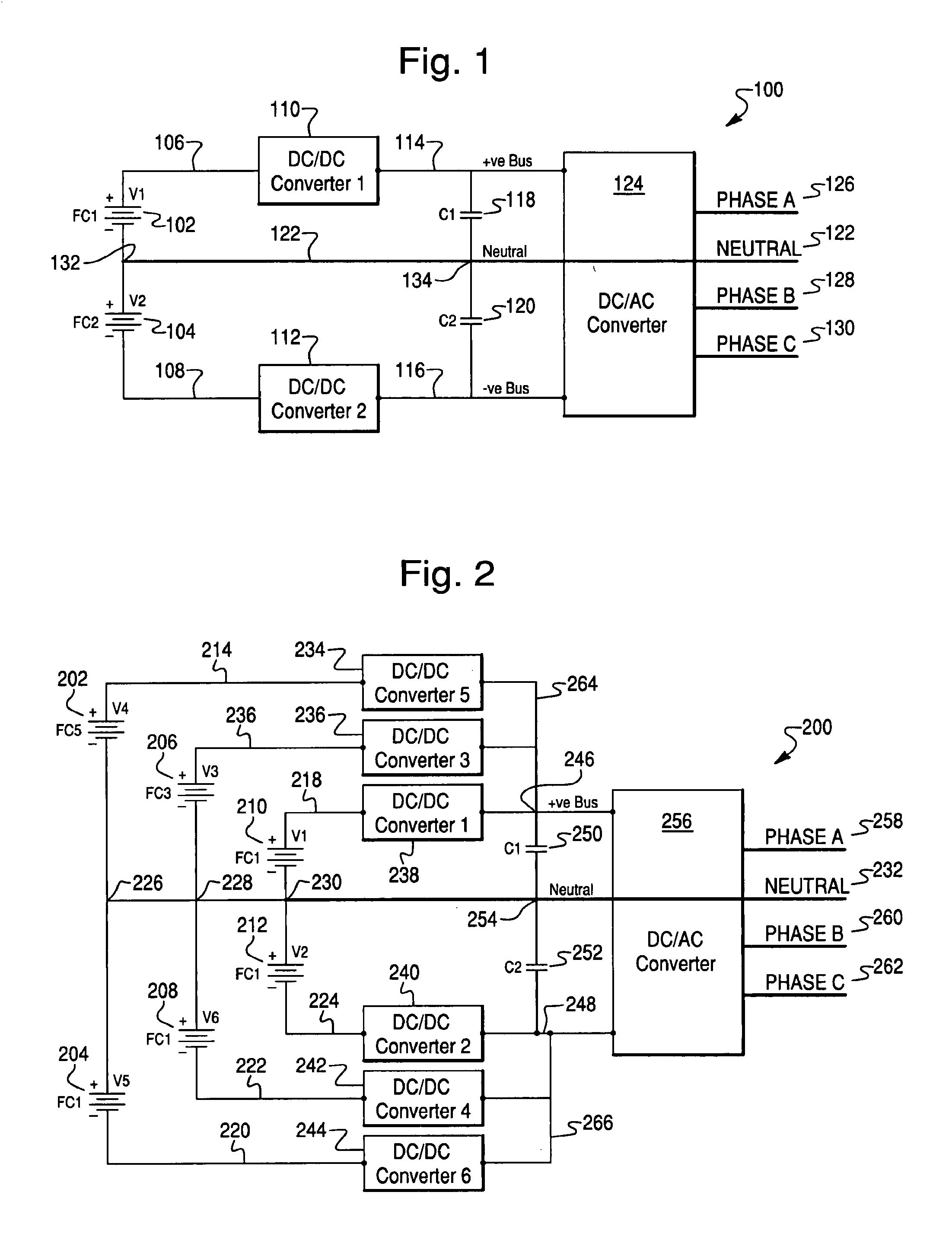
[0024]Referring to FIG. 1, a fuel cell power conversion system architecture embodiment 100 with two parallel busses is shown. The architecture 100 is illustrated from fuel cells to three-phase power output, and may be referred to as a type of power conversion module, where “module” is a general term referring to a group of system components. The system 100 comprises two fuel cell segments 102 and 104 containing one or more fuel cells and having respective connections 106 and 108 to DC / DC converters 110 and 112. DC / DC converters 110 and 112 are similar converters. They are usually boost converters. DC / DC converters 110 and 112 have respective output busses 114 and 116, referred to hereinafter as the +ve and −ve busses, respectively. Each circuit branch having a DC / DC converter and extending, for example, from connection 106 through DC / DC converter 110 and ending with bus 114 may be referred to as a DC / DC converter branch. If the fuel cell segments are included, the terminology “stack...
second embodiment
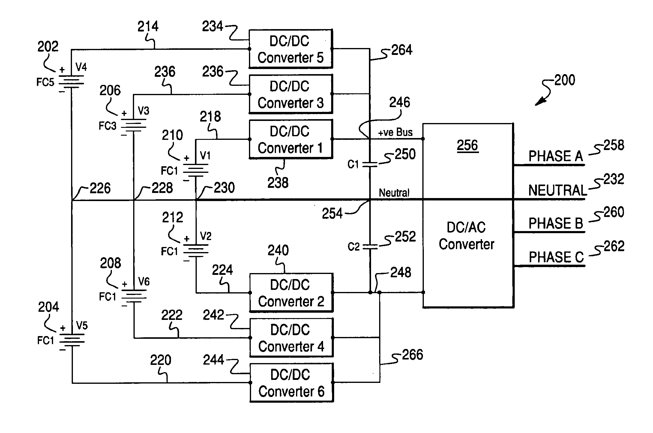
[0029]Referring now to FIG. 2, a second embodiment in the form of a fuel cell power conversion system architecture 200 is shown. The architecture 200 may also be referred to as a power conversion module. The embodiment of FIG. 2 comprises three pairs of fuel cell segments. Fuel cell segments 202 and 204 are paired in an arrangement similar to that described with reference to FIG. 1. Fuel cell segments 206 and 208, as well as fuel cell segments 210 and 212 are also similarly paired. As an example, fuel cell segment 202 is connected with its negative terminal to node 226, while fuel cell segment 204 is connected with its positive terminal to node 226. Fuel cell segments 206 and 210 are also connected with their negative terminals to nodes 228 and 230 respectively. Nodes 228 and 230 are connected to nodes 226 and 254 as well as neutral line 232, and are at the same electrical potential. Fuel cell segments 208 and 212 are connected with their positive terminals to nodes 228 and 230 resp...
PUM
| Property | Measurement | Unit |
|---|---|---|
| power | aaaaa | aaaaa |
| voltage | aaaaa | aaaaa |
| current | aaaaa | aaaaa |
Abstract
Description
Claims
Application Information
 - R&D
- Intellectual Property
- Life Sciences
- Materials
- Tech Scout
- Unparalleled Data Quality
- Higher Quality Content
- 60% Fewer Hallucinations
Browse by: Latest US Patents, China's latest patents, Technical Efficacy Thesaurus, Application Domain, Technology Topic, Popular Technical Reports.
© 2025 PatSnap. All rights reserved.Legal|Privacy policy|Modern Slavery Act Transparency Statement|Sitemap|About US| Contact US: help@patsnap.com


