
Liquid crystal display device

a liquid crystal display and liquid crystal technology, applied in static indicating devices, instruments, optics, etc., can solve the problems of reducing the contrast ratio of display devices, not easy to apply blue phase liquid crystal in a common apparatus, and difficult to apply it in a practical produ

Active Publication Date: 2011-11-10
AU OPTRONICS CORP
View PDF3 Cites 21 Cited by
  • Summary
  • Abstract
  • Description
  • Claims
  • Application Information

AI Technical Summary

Benefits of technology

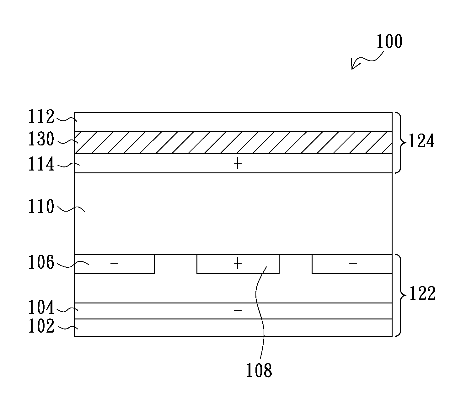
[0011]The present invention provides a liquid crystal display device, which is capable of solving the problem of light leakage in dark state of polymer stabilized positive blue phase liquid crystal.
[0014]Accordingly, the present invention employs at least one pair of electrodes to provide a horizontal electric field for driving the polymer stabilized positive blue phase liquid crystal to increase the light transmittance thereby controlling the brightness of liquid crystal display devices. In addition, the present invention also employs at least one pair of electrodes to provide a vertical electric field for compensating the optical isotropy of the polymer stabilized positive blue phase liquid crystal such that the polymer stabilized positive blue phase liquid crystal have excellent optical isotropy characteristic when there is no horizontal electric field is applied. As a result, light leakage in the dark state is greatly reduced.

Problems solved by technology

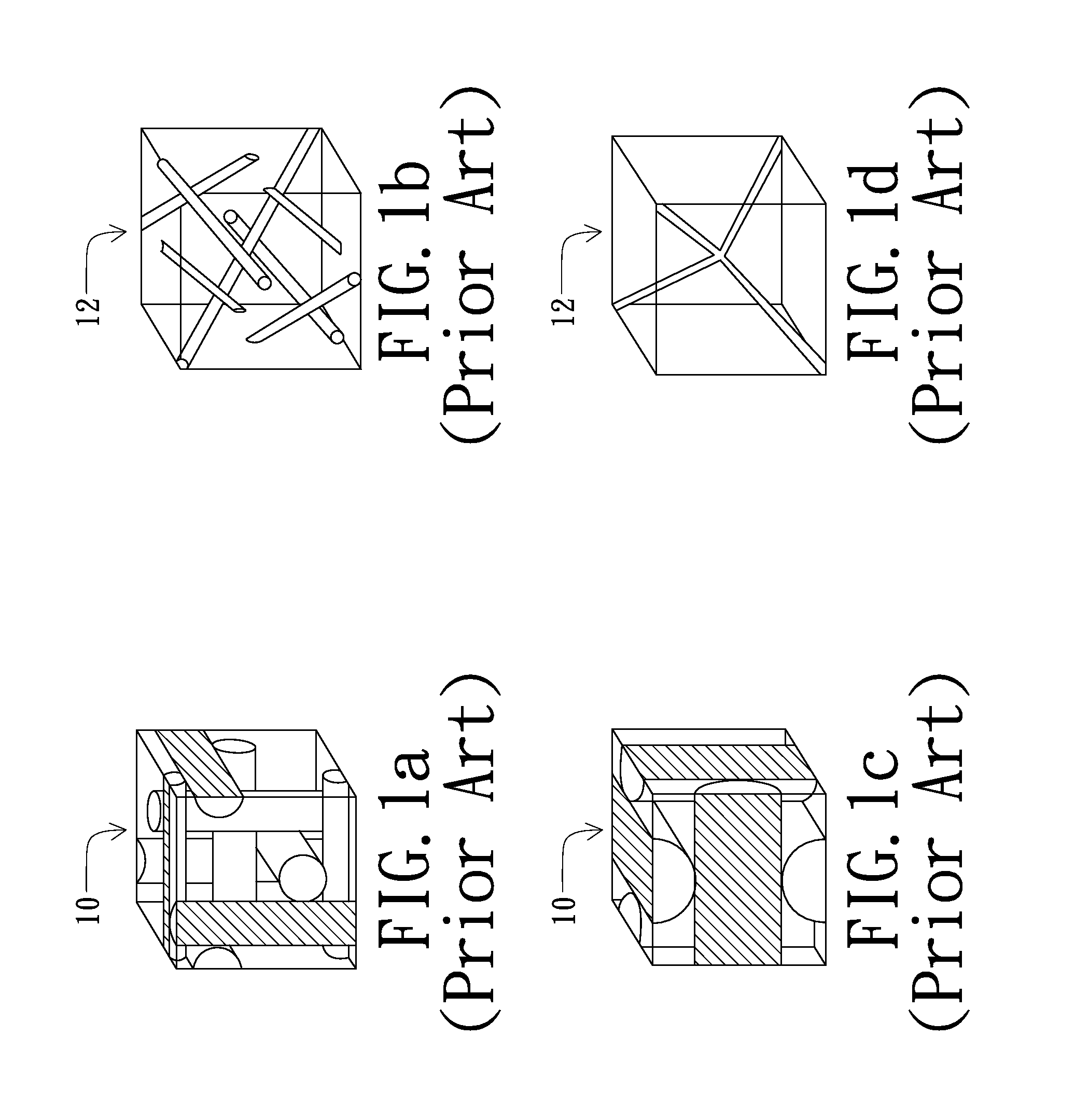
However, blue phase liquid crystal is unstable, and thus can only exist in a very narrow temperature range having a width of about 1° C. Therefore, blue phase liquid crystal can not be easily applied in a common apparatus.
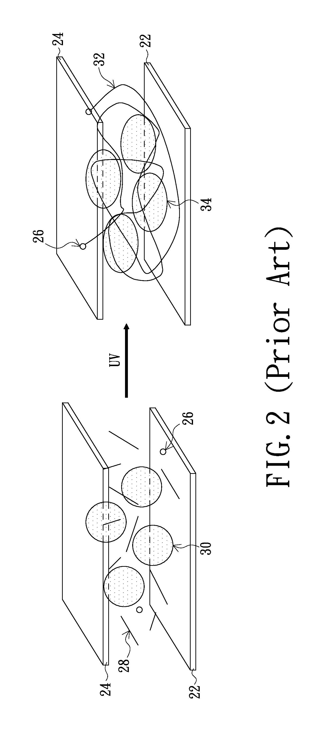
But at this time, the blue phase liquid crystal 30 can only exits in a very narrow temperature range, and it is not easy to apply it in to a practical product.
However, in practice, conventional polymer stabilized positive blue phase liquid crystal 34 can not demonstrate perfect isotropic property when there is no voltage applied; that is, the birefringence rate is greater than zero (Δn=n / / −n⊥>0), and thus usually cause the problem of light leakage in dark state resulting in decreasing of the contrast ratio of display devices.

Method used


Image

  • Liquid crystal display device
  • Liquid crystal display device
  • Liquid crystal display device

Examples


Embodiment Construction

[0026]The present invention utilizes the double-sided electrode design to produce horizontal and vertical electric fields in liquid crystal cell. The horizontal electric field enables the liquid crystal cell to display an excellent bright state, and the vertical electric field enables the liquid crystal cell to display an excellent dark state. Hereinafter, the liquid crystal display device of the present invention will be described in detail referring to embodiments accompanying with figures. However, the illustrated embodiments are not intended to be used to limit the scope of the present invention, and the description of the structure and operating procedure are not intended to be used to limit the operation procedure of the present invention. Any structure obtained from re-assembling the features and having equivalent functions are both the scope of the present invention. The figures are illustrative and are not drawn according to actual scales.

[0027]FIG. 4 is a schematic view sh...


PUM

PropertyMeasurementUnit
Electrical conductoraaaaaaaaaa
Electric fieldaaaaaaaaaa

Abstract

A liquid crystal display device includes a first substrate, a second substrate, a first vertical electrode, a second vertical electrode, a first pixel electrode, a first counter electrode, and a liquid crystal layer. The second substrate is disposed to be opposite to the first substrate, the liquid crystal layer is interposed between the first and second substrates. The liquid crystal layer includes polymer stabilized positive blue phase liquid crystal. The first vertical electrode is at an inner side of the first substrate, and faces the second substrate. The second vertical electrode is at an inner side surface of the second substrate and faces the first vertical electrode. The second vertical electrode and the first vertical electrode have different electrical potentials thus form a vertical electric field perpendicular to the first substrate and the second substrate. The first pixel electrode is at the inner side of the first substrate and faces the second substrate. The first counter electrode is at an inner side of the first substrate. The first pixel electrode and the first counter electrode have different electrical potentials. The first pixel electrode and the first counter electrode provide a horizontal electric field parallel to the first substrate and the second substrate.

Description

CROSS-REFERENCE TO RELATED APPLICATIONS[0001]This application claims the right of priority based on Taiwan Patent Application No. 098142983 entitled “Liquid Crystal Display Device”, filed on Dec. 15, 2009, which is incorporated herein by reference and assigned to the assignee herein.BACKGROUND[0002]1. Technical Field[0003]The present invention relates to liquid crystal display devices, and in particular to a liquid crystal display device having a blue phase liquid crystal layer.[0004]2. Related Art[0005]Liquid crystal display devices have become the mainstream of development of display devices in recent years due to the advantages of low operation voltage, no radiation scattering, light weight and small size. Conventional liquid crystal display devices usually employ nematic crystal to change polarizing direction or status of the passing light, and employ a polarizer plate to convert the different polarizing status into bright / dark contrast for displaying; and thus the response time...

Claims


Application Information

Patent Timeline
IPC IPC(8): G02F1/133
CPCG02F1/134363G02F1/137G02F2001/13793G02F2001/13775G02F2001/134381G02F1/134381G02F1/13775G02F1/13793
Inventor TSAI, CHENG-YEHHUANG, TAI-HSIANGCHEN, PO-LUN
Owner AU OPTRONICS CORP
Learn More