Electrical system for starting up aircraft engines

a technology for aircraft engines and electrical systems, applied in the direction of electric devices, control of dynamo-electric converters, transportation and packaging, etc., can solve the problems of high cost, high cost, and large equipment weight, and achieve the effect of reducing equipment weight and high reliability

Active Publication Date: 2011-11-10
SAFRAN ELECTRICAL & POWER
View PDF6 Cites 21 Cited by
  • Summary
  • Abstract
  • Description
  • Claims
  • Application Information

AI Technical Summary

Benefits of technology

[0005]The present invention thus proposes to mitigate the above-mentioned drawbacks and more particularly to minimize the weight of equipment needed for enabling propulsion engines and the APU of an aircraft to be started from a power network or from a battery, with a high level of reliability for re-starting in flight, and if necessary also with a dispatch reliability level that is sufficiently high for starting on the ground.

Problems solved by technology

Nevertheless, such an addition uses up weight and volume and thus represents additional costs.
Conventional battery voltages lie in the range 24 Vdc to 48 Vdc so this boost DC / DC converter comprises multiple stages or cells, possibly including electrical isolation, and necessarily presents a high boost ratio, typically greater than 10, and thus constitutes equipment that is complex and difficult to regulate, heavy, and voluminous, and thus ends up being particularly expensive.

Method used


Image

  • Electrical system for starting up aircraft engines
  • Electrical system for starting up aircraft engines
  • Electrical system for starting up aircraft engines

Examples


Embodiment Construction

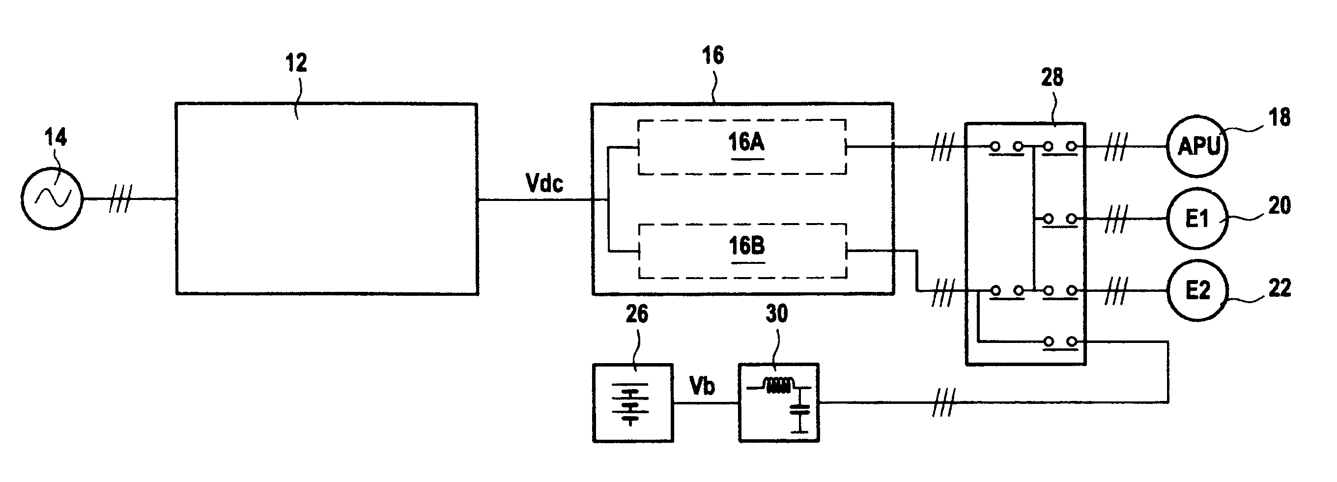
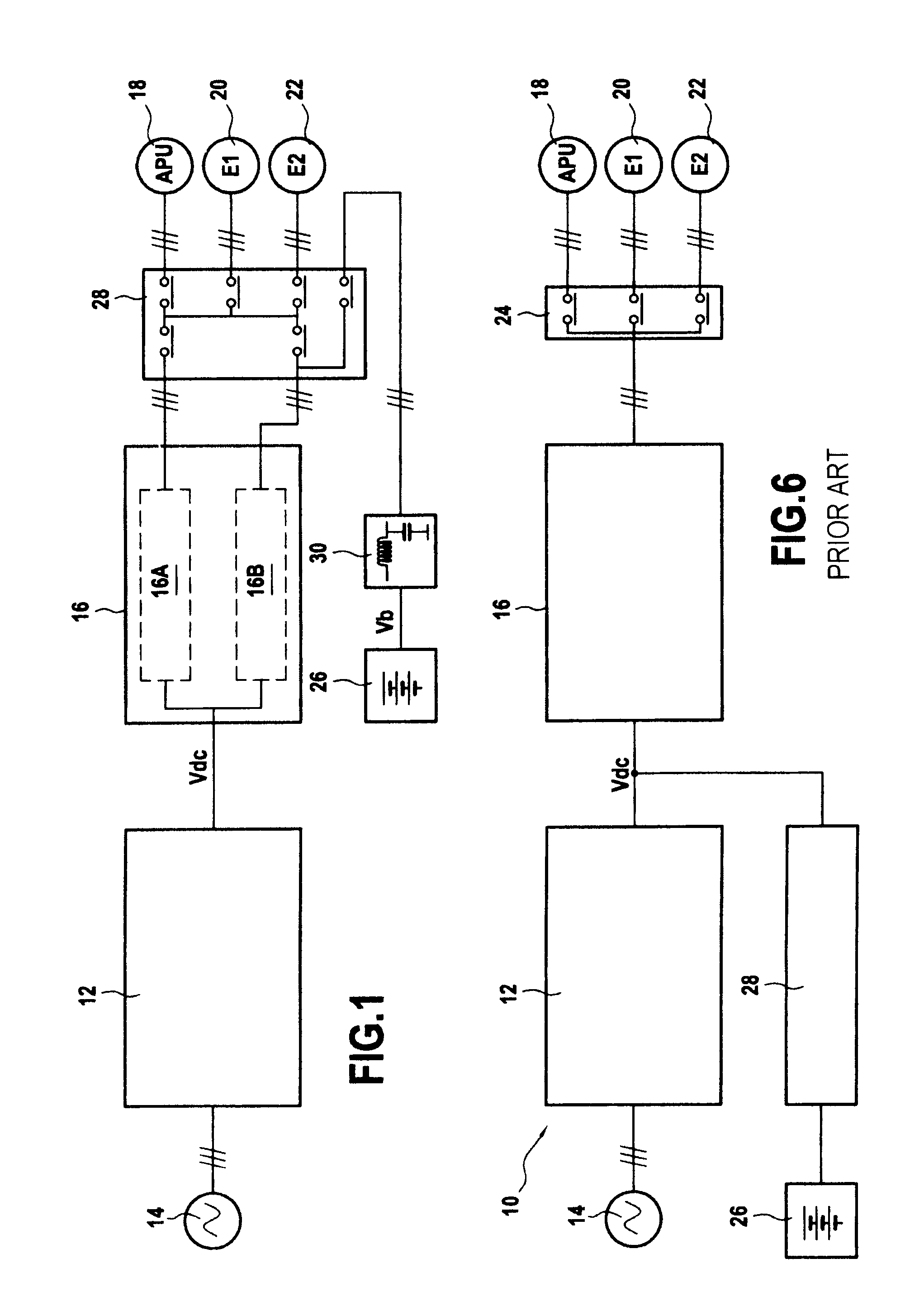
[0024]FIG. 1 is a block diagram showing the electrical system of the invention for starting engines.

[0025]As in prior art systems, there can be seen the AC / DC rectifier 12 used for rectifying the alternating voltage delivered by the power supply network 14, advantageously a three-phase network, and followed in like manner by a DC / AC converter 16 powering various starter-generators 18, 20, 22 via a connection matrix in which the positions of the various contactors shown by way of example enables various different operating modes to be implemented. Nevertheless, the matrix 28 is significantly different in order to incorporate an additional channel coming from the battery 26 that, unlike prior art systems, is not followed by a DC / DC converter but merely by a conventional filter 30 having its output connected directly to the output of the DC / AC converter via the connection matrix 28. It should be observed that the omission of the DC / DC converter reduces the number of semiconductor devic...


PUM


Abstract

An electrical system (18, 20, 22) for starting an engine, the system comprising: an AC/DC rectifier (12) powered by an AC power network (14) to deliver a first DC voltage Vdc, and a DC/AC converter module (16) for delivering an AC voltage for starting the engine from said first DC voltage Vdc, the system comprising k n-phase inverters arranged in parallel (k>1) and each delivering power no greater than half a maximum power Pmax required for starting the engine, and the two power supply lines of each of the inverters are connected to an electronic protection device receiving the first DC voltage Vdc, and the n outputs of each of the inverters delivering the AC voltage for starting the engine via n respective series inductors.

Description

FIELD OF THE INVENTION[0001]The present invention relates to the field of power converters, and it relates more particularly to systems for starting aeroengines.PRIOR ART[0002]In the field of aviation, it is known to start propulsion engines and the auxiliary power unit (APU) of an aircraft from an electrical starter system of the type shown in FIG. 6. Such a system 10 conventionally comprises an alternating current to direct current (AC / DC) rectifier 12 for obtaining a DC voltage Vdc from the power supply network 14 on board the aircraft or from a generator unit on the ground, followed by a DC / AC converter 16 for powering the starter-generators 18, 20, 22 of the associated engines (via a connection matrix 24) while the engines are being started. The DC / AC converter 16 generally comprises an inverter having a power level “Pn” sufficient to start a propulsion engine on the ground. In order to improve reliability concerning the ability to re-start an engine in flight and the availabil...

Claims


Application Information

Patent Timeline
Patent Type & Authority Applications(United States)
IPC IPC(8): B60L1/00
CPCH02P1/00H02M7/493
Inventor DE WERGIFOSSE, ERIC
Owner SAFRAN ELECTRICAL & POWER
Why Eureka
Try Eureka