Variable valve actuation apparatus of internal combustion engine
a valve actuator and internal combustion engine technology, applied in the direction of machine/engine, manufacturing tools, solventing apparatus, etc., can solve the problem of comparatively great hammering noise, and achieve the effect of suppressing the occurrence of hammering noise during operation
- Summary
- Abstract
- Description
- Claims
- Application Information
AI Technical Summary
Benefits of technology
Problems solved by technology
Method used
Image
Examples
first embodiment
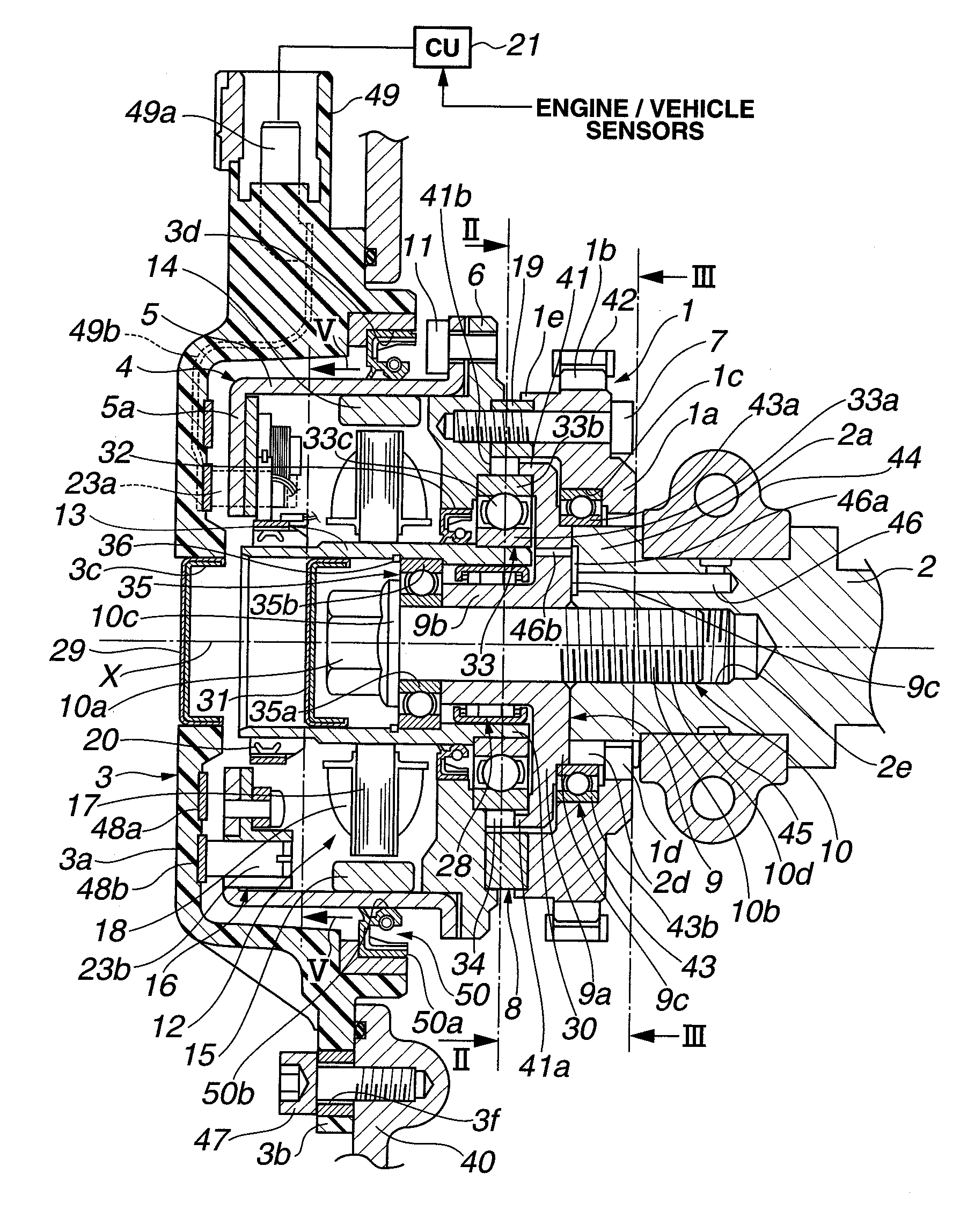
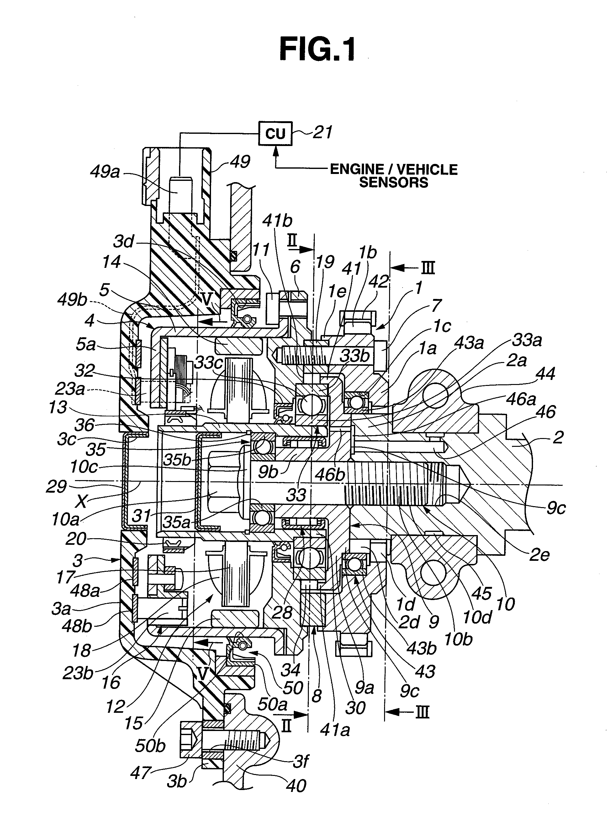
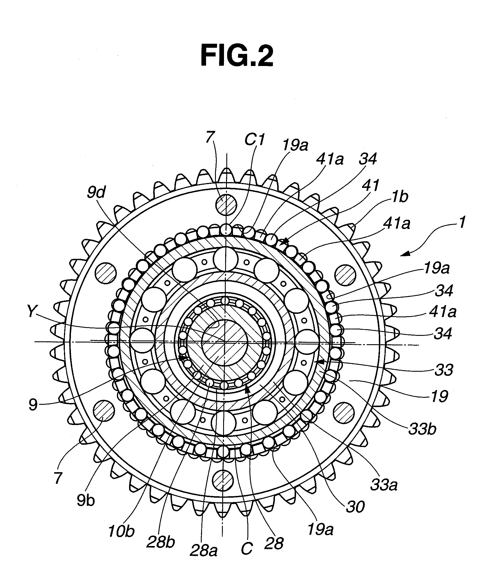
[0024]Referring now to the drawings, particularly to FIGS. 1-5, the variable valve actuation apparatus of the embodiment is exemplified in a variable valve timing control (VTC) device of an internal combustion engine. In the shown embodiment, the VTC device is applied to a valve operating system of the intake-valve side of the internal combustion engine. In lieu thereof, the VTC device may be applied to a valve operating system of the exhaust-valve side of the engine.
[0025]As shown in FIGS. 1-5, the VTC device of the embodiment is comprised of a timing sprocket 1 (a drive rotary member) that rotates in synchronism with rotation of an engine crankshaft, a camshaft 2 rotatably supported on a cylinder head (an engine body not shown) through camshaft-journal bearings 44 and driven by torque transmitted from timing sprocket 1, a cover member 3 (a stationary member) laid out in front of the timing sprocket 1 and bolted to a chain cover 40, and a phase converter 4 installed between timing ...
experimental example
[0077]The reason for the specified setting on the allowable clearance range Q of very small clearance C1 (e.g., 10 μm-40 μm), is based on experimental results assured by the inventors of the present invention. The details of these experimental results are hereunder described in detail in reference to the graphs of FIGS. 9-12 showing several experimental results, plotted while setting and changing the previously-noted clearance C1 to approximately 5 μm, 10 μm, 15 μm, 20 μm, 25 μm, 30 μm, 35 μm, 40 μm, 45 μm, and 50 μm, in that order. FIG. 9 shows the relationship between the clearance C1 (unit: μm) of speed reducer 8 (exactly, a very small radial clearance between the circumference of roller 34 and the inner face 19b of annular member 19) and a noise level (unit: dB) of the whole VTC device. FIG. 10 shows the relationship between the clearance C1 (unit: μm) and a vibration in terms of vibration acceleration (unit: G) of the whole VTC device. FIG. 11 shows the relationship between the...
second embodiment
[0085]Referring to FIGS. 13 and 14A-14C, there are shown a series of modified clearance-adjustment procedures of speed reducer 8 of the variable valve actuation apparatus of the second embodiment. The fundamental construction and operation of the variable valve actuation apparatus (the VTC device) of the second embodiment are identical to those of the first embodiment. The modified clearance-adjustment procedures of FIG. 13 are somewhat different from the clearance-adjustment procedures of FIG. 7, as follows.
[0086]According to the clearance-C1-adjustment procedures of FIG. 7, considerably severe very small clearance adjustment of speed reducer 8 is performed by replacing or exchanging the reference roller set with a different-size roller set that ensures the allowable clearance range (i.e., 10 μm-40 μm), only when, with the reference roller set installed between the outer race 33b of the first ball bearing 33 and the waveform internal toothed portion 19a of annular member 19, the ac...
PUM
| Property | Measurement | Unit |
|---|---|---|
| Length | aaaaa | aaaaa |
| Length | aaaaa | aaaaa |
| Diameter | aaaaa | aaaaa |
Abstract
Description
Claims
Application Information
 - R&D Engineer
- R&D Manager
- IP Professional
- Industry Leading Data Capabilities
- Powerful AI technology
- Patent DNA Extraction
Browse by: Latest US Patents, China's latest patents, Technical Efficacy Thesaurus, Application Domain, Technology Topic, Popular Technical Reports.
© 2024 PatSnap. All rights reserved.Legal|Privacy policy|Modern Slavery Act Transparency Statement|Sitemap|About US| Contact US: help@patsnap.com


