
Configuration engine for a process simulator

a technology of process simulator and configuration engine, which is applied in the direction of instruments, geometric cad, computing, etc., can solve the problems of increasing complexity of process facilities, limited information, and general impracticality of using templates for entire processes, so as to reduce time

Active Publication Date: 2011-10-27
ASPENTECH CORP
View PDF8 Cites 20 Cited by
  • Summary
  • Abstract
  • Description
  • Claims
  • Application Information

AI Technical Summary

Benefits of technology

"The invention is a computer modeling system that allows users to quickly create a rigorous simulation model of a processing facility design using limited data. This system includes an input module for user specification of the design, a processor routine for forming an input data set, and a simulation modeler for modeling the design. The system can also produce a rigorous simulation model that can be user-edited and adapted. The invention reduces the time required to create a simulation model, allowing for more design alternatives to be evaluated."

Problems solved by technology

In the design of a process plant, such as, for example, an oil and gas facility, a gas cleaning plant, a carbon dioxide capture facility, a liquefied natural gas (LNG) plant, an oil refinery, or a petrochemical facility (e.g., an ethylene plant), companies need to make major multi-million dollar investment decisions about the most appropriate capacity, location, and functionality of the facility, typically with very limited information, particularly at preliminary stages of the design.
The use of templates is generally impractical for entire processes, due to large variations in process conditions and constraints for each specific process.
At present, the design of process facilities is becoming more complex, due to many factors such as, for example, more complex feedstocks, higher feed pressures and temperatures, the presence of trace elements, tighter product quality specifications, tighter environmental and safety constraints, and more volatile market conditions and global economic factors.
The added complexity increases the necessity to scrutinize design options more thoroughly earlier in the design cycle, in order to accurately assess project risks and avoid design rework at later stages of the design cycle or the procurement of inappropriate or incorrect equipment.
Present design methods are not sufficiently rigorous in taking into account the underlying thermodynamics, physical properties, and unit operation and equipment design methods to meet the increasing technical complexity of modern process design and the increasing scrutiny of technical risks.
Such data is generally limited or not available at the early stages of process design.
Furthermore, the manual configuration by the user of plant topology and connectivity is quite time consuming, making it impractical to create a rigorous process simulation model of each potential design alternative.

Method used


Image

  • Configuration engine for a process simulator
  • Configuration engine for a process simulator
  • Configuration engine for a process simulator

Examples


Embodiment Construction

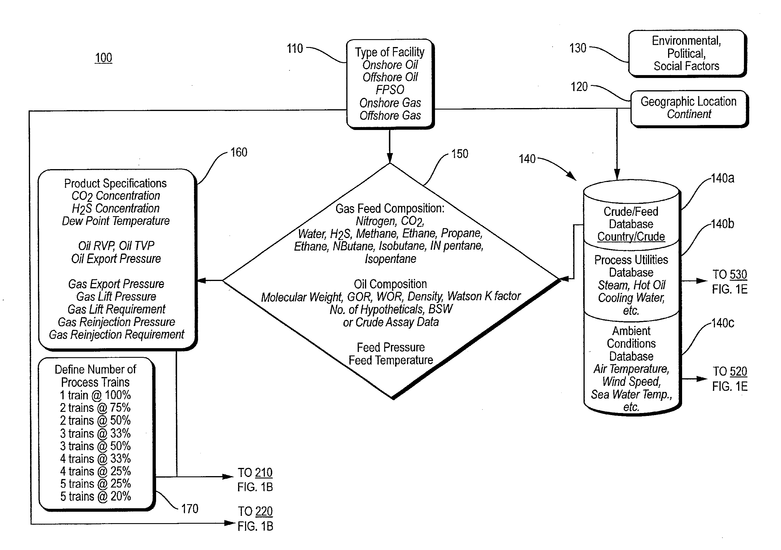
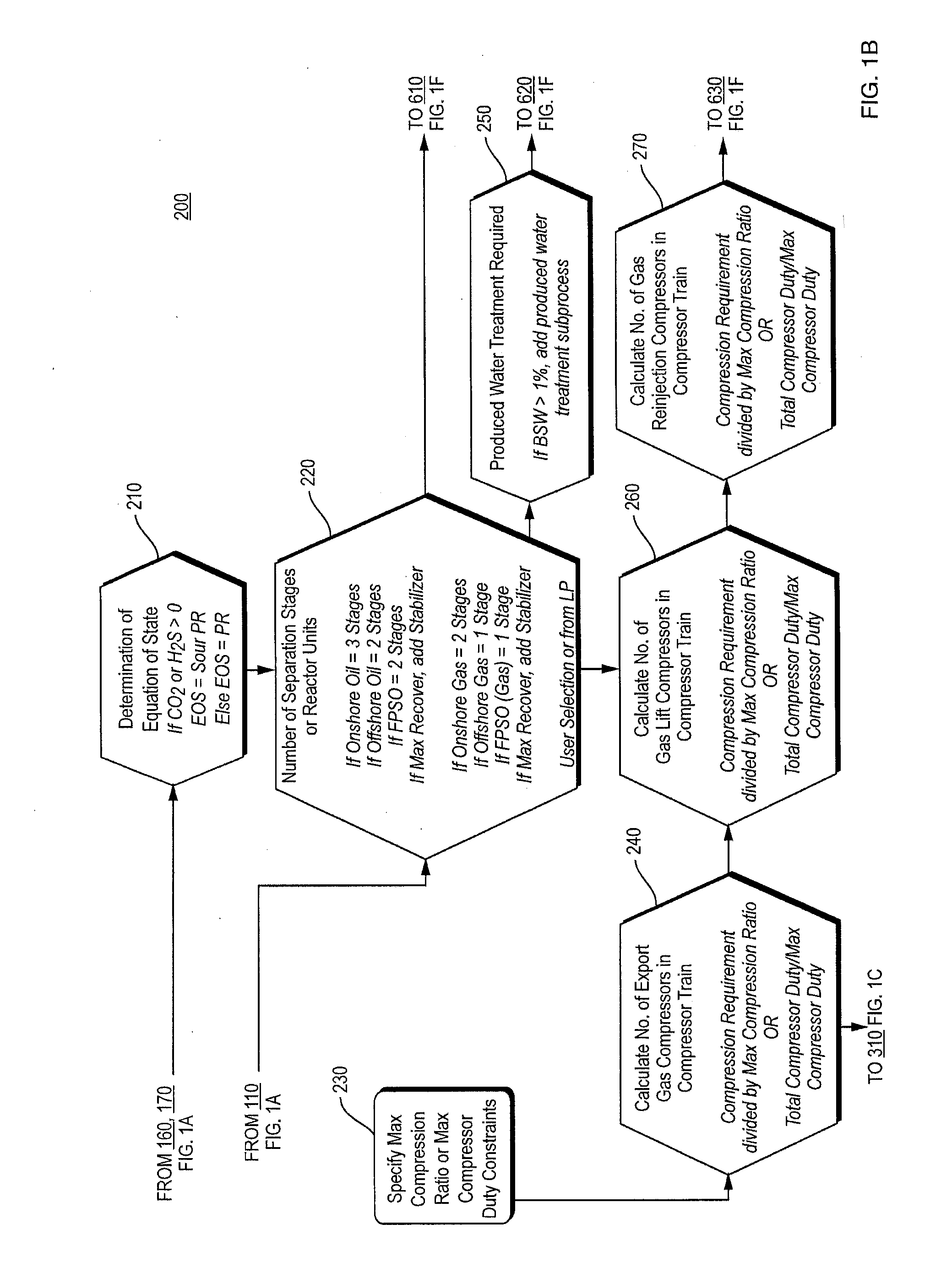
[0041]A description of an example embodiment of the invention illustrating the design of an oil and gas separation facility follows.

[0042]The conceptual design of an exploration and production (E&P) asset involves the development of many scenarios and options. This engineering process is known as field development or appraisal. Preliminary seismic data or well test data is used by the reservoir and geophysics groups to build a preliminary reservoir model which predicts the production rates of gas, oil, condensate, and water over the projected life of the field.

[0043]Due to the preliminary nature of the source data, a number of scenarios are generated and assigned with different probabilities (e.g., 10, 90, and 50%). These are called the P10, P90, and P50 cases. As will be made clearer below, probabilities are used to weigh investment risks, which in turn give rise to the need to model so many scenarios.

[0044]The appraisal and conceptual design group or field development teams are ta...


PUM


Abstract

A computer modeling apparatus includes an input module enabling user specification of a subject facility design based on limited data. The subject facility design includes design alternatives, and a processor routine coupled to the input module and responsive to the user specification by forming an input data set to a rigorous simulation modeler to model the subject facility design. The rigorous simulation modeler requires input beyond the limited data. The processor routine enables execution of the simulation modeler. The computer modeling apparatus further includes an interface member that enables the production of a rigorous simulation model of the subject facility design from the simulation modeler. The subject facility is one of an oil processing facility, a gas processing facility, an oil and gas separation facility, or a chemical processing facility.

Description

RELATED APPLICATION[0001]This claims the benefit of U.S. Provisional Application No. 61 / 326,906, filed on Apr. 22, 2010.[0002]The entire teachings of the above application are incorporated herein by reference.BACKGROUND OF THE INVENTION[0003]In the design of a process plant, such as, for example, an oil and gas facility, a gas cleaning plant, a carbon dioxide capture facility, a liquefied natural gas (LNG) plant, an oil refinery, or a petrochemical facility (e.g., an ethylene plant), companies need to make major multi-million dollar investment decisions about the most appropriate capacity, location, and functionality of the facility, typically with very limited information, particularly at preliminary stages of the design. There are many potential configuration and design options, making it difficult to identify viable options and to compare them on a consistent basis, so that the optimal design can be selected for the best match to business criteria and operational constraints, and...

Claims


Application Information

Patent Timeline
Patent Type & Authority Applications(United States)
IPC IPC(8): G06F17/50
CPCG06F17/5004G06F2217/80G06F2217/16G06F30/13G06F2111/10G06F2119/08
Inventor BLEACKLEY, DAVIDVAN WASSENHOVE, WILLEM
Owner ASPENTECH CORP
Learn More