
Fractionation system and methods of using same

a technology of fracturing system and well, which is applied in the direction of fluid removal, earth drilling and mining, borehole/well accessories, etc., can solve the problems of safety hazards, one or more operators can be subject to inclement weather, and potential safety risks, and achieve the effect of conserving spa

Inactive Publication Date: 2011-10-27
BROUSSARD II WAYNE F
View PDF1 Cites 61 Cited by
  • Summary
  • Abstract
  • Description
  • Claims
  • Application Information

AI Technical Summary

Benefits of technology

In a preferred embodiment of the invention, one or more of the valves and / or one or both of the chokes can be actuated wirelessly, thereby enabling a single remote operator to cause the fractionation system to perform any desired function, and to regulate the pressure and flow rates throughout the system, without requiring hydraulic or electrical lines, or other conduits that undesirably occupy space on a rig floor, and without requiring the presence of any personnel on the rig floor, thereby providing an immense safety benefit over conventional systems. While manually actuatable units could also be used to control the valves and / or chokes, as could one or more umbilical units, wireless control enables a single remote operator, located away from the rig floor, to monitor and control the state of one or more valves or chokes within the system, pressure within one or more portions of the system, the remaining power of a power source used to power one or more portions of the system, or combinations thereof.
Embodiments of the present invention thereby provide fractionation systems and related methods that can perform the functions of multiple manifolds normally required for a fracturing operation, while accommodating flow rates exceeding that of conventional manifolds using only a single power unit, and enabling wireless control, thereby advantageously conserving spaced on a rig floor while eliminating the need for on-site personnel to manipulate parts of the system.

Problems solved by technology

Additionally, each manifold requires a series of hydraulic conduits or similar connections to enable actuation of the manifold, which further consumes limited space proximate to a wellhead and can create a safety hazard.
Often, the one or more operators can be subject to inclement weather, and potential safety risks when manipulating the manifolds.
A typical fractionation system, especially a system incorporating a second choke, is extremely large, cumbersome, and expensive, containing a large number of valves and connectors, and requiring a large number of hoses and conduits to ensure sufficient electrical and / or hydraulic connections.
Additionally, most fractionation manifolds are difficult and time consuming to properly install, each valve and component requiring precise alignment using cranes and other devices adapted for manipulation of the heavy components.
Further, most fractionation manifolds are limited regarding the orientation with which components can be installed and engaged, which can become a hindrance on offshore rigs and other drilling sites where space is limited.
Also, most fractionation manifolds require on-site personnel to actuate valves, chokes, and other parts of the manifolds, increasing the time required for each operation, and the inherent risk to the operators.
Also, a typical fractionation system is limited to a flow rate of approximately 30 barrels of fluid per minute.
When additional flow is necessary, multiple manifolds are used, increasing the time, expense, and space required, and necessitating additional cumbersome installation and operating procedures necessary to fracture and produce a well.

Method used


Image

  • Fractionation system and methods of using same
  • Fractionation system and methods of using same
  • Fractionation system and methods of using same

Examples


Embodiment Construction

Before explaining selected embodiments of the present invention in detail, it is to be understood that the present invention is not limited to the particular embodiments depicted and described, and that the present invention can be practiced or carried out in various ways.

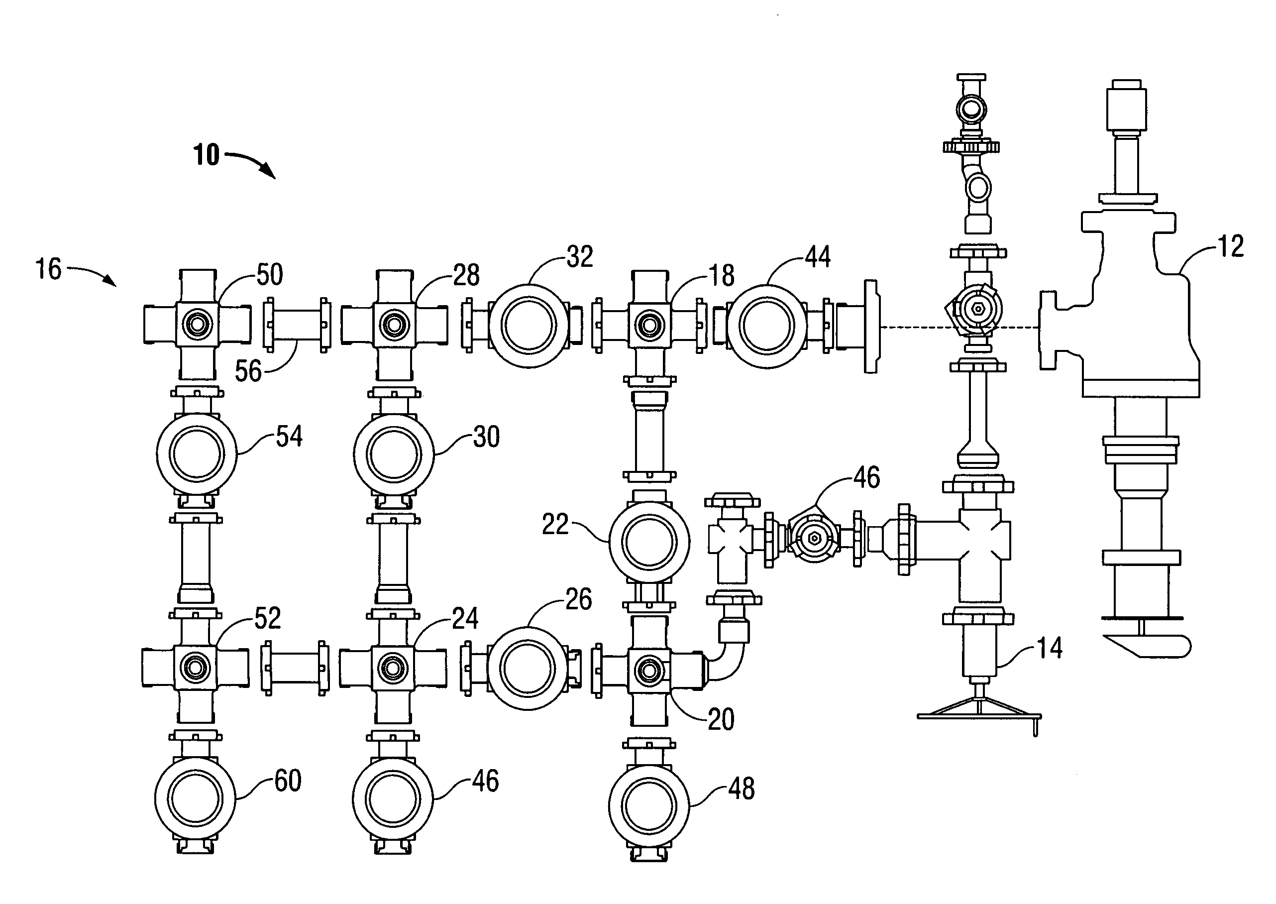
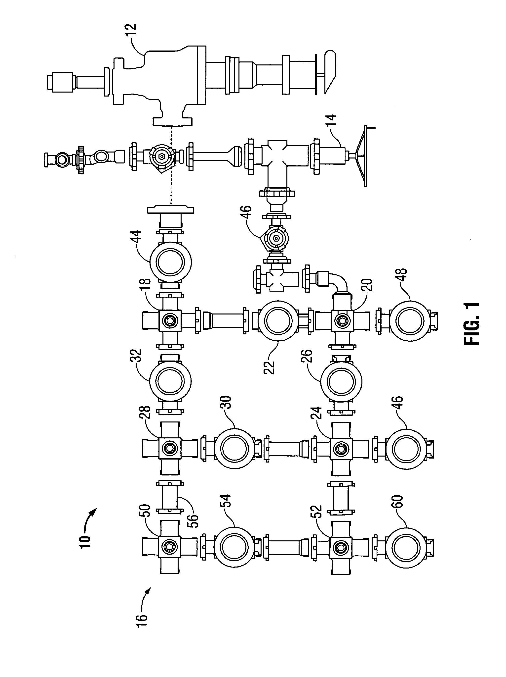
Referring now to FIG. 1, a diagrammatic top view of an embodiment of a fractionation system useable within the scope of the present disclosure is shown. The depicted embodiment includes a fractionation manifold (10) engaged with a primary choke (12), a secondary choke (14), and a shotgun manifold (16). Each of the manifolds (10, 16) is shown including numerous connectors having valves therebetween, while each of the chokes (12, 14) can include valves and other controllable elements, as known in the art. In a preferred embodiment of the invention, any of the valves and / or chokes are controllable wirelessly, enabling a single remote operator to monitor and control the pressure and flow rate throughout the system, and...


PUM


Abstract

A fractionation system is disclosed, the system having a fractionation manifold with a plurality of connectors in fluid communication with one another and a plurality of valves disposed adjacent the connectors for selectively flowing fluid through the manifold. The connectors define a plurality of exterior ports for communication with wellstrings and fracturing fluid sources. A primary choke in communication with a tubing string and a secondary choke in communication with a casing string can be engaged with exterior ports, the secondary choke useable as a backup choke and for inducing sandouts. The present system can achieve a flow rate of up to 80 barrels per minute, or more, using only a single manifold and single power unit, and can be wirelessly operated. System components can incorporate self-aligning, self-positioning skids, or alternatively, the system can be transported using a single skid to facilitate portability and installation.

Description

FIELDThe present disclosure relates, generally, to fractionation systems for fracturing a well and related methods of use.BACKGROUNDTo increase production of a well, it is often necessary to fracture the well, which is performed by flowing fracturing fluid into the earth to mechanically create cracks in the ground. Fracturing fluid typically includes a liquid mixed with sand, small ceramic beads, or similar proppant material, which creates pressure within the well as the fluid accumulates, until the pressure causes cracks to form in the earth, or causes existing cracks in the earth to widen, thereby increasing the flow of hydrocarbons from the well.Conventionally, when fracturing a well, numerous manifolds, i.e. a pumping manifold, a flowback manifold, a choke manifold, and other manifolds, must be installed at the wellhead surface, which can require six to eight hours, or longer, numerous personnel, and a large amount of space on a rig floor. Additionally, each manifold requires a ...

Claims


Application Information

Patent Timeline
Patent Type & Authority Applications(United States)
IPC IPC(8): E21B43/26E21B43/00
CPCE21B43/26E21B34/02E21B43/2607
Inventor BROUSSARD, II, WAYNE F.
Owner BROUSSARD II WAYNE F
Learn More