
Double-layer headbox for a machine for producing a double-layer fibrous web

a technology of fibrous web and headbox, which is applied in the direction of machine wet end, textiles and papermaking, papermaking, etc., can solve the problems of increasing raw material and energy costs, increasing the demands on stream stability,

Inactive Publication Date: 2011-10-27
VOITH PATENT GMBH
View PDF4 Cites 4 Cited by
  • Summary
  • Abstract
  • Description
  • Claims
  • Application Information

AI Technical Summary

Benefits of technology

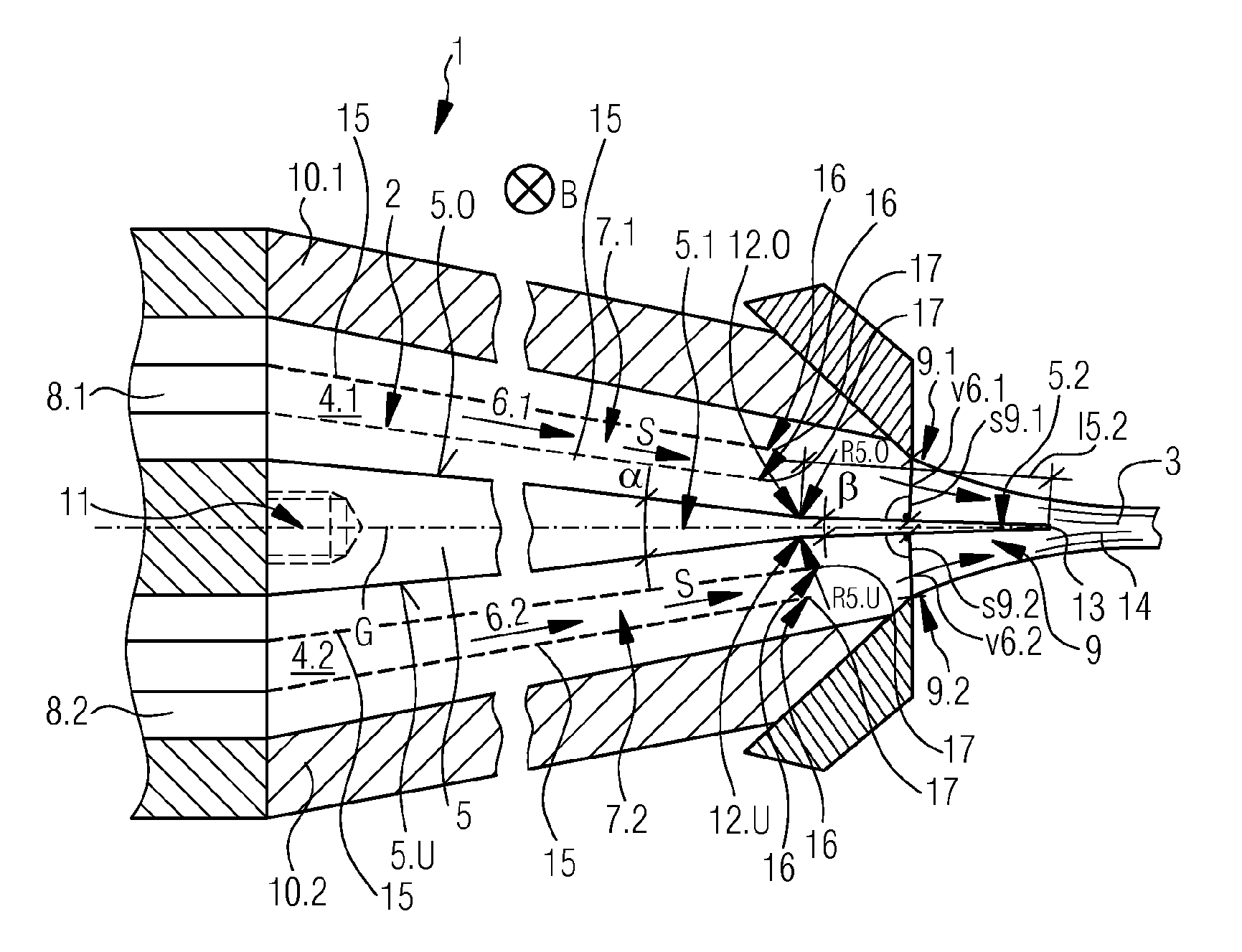
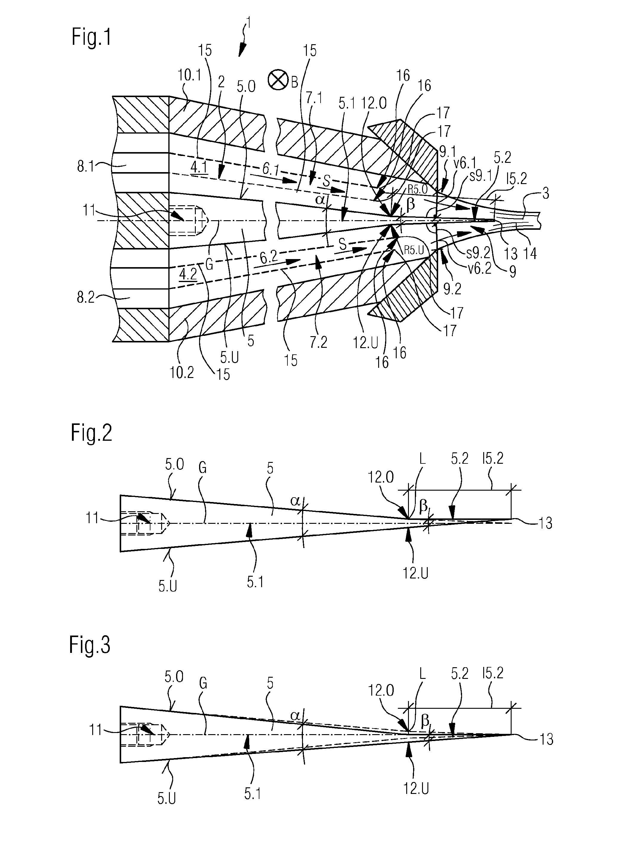
[0011]The separating wedge of the inventive double-layer headbox provides the advantage that layer integrity in height direction is clearly improved compared to known multi-layer headboxes. The reason for this is primarily that the angle of impact of the two fibrous suspension streams at their confluence at the separating wedge end is clearly reduced. Combined with this is a reduction of the turbulences which develop in the fibrous suspension streams, resulting in an improvement of the layer integrity in height direction.
[0012]The turbulences developing in the two fibrous suspension streams also substantially influence the coverage qualities of the two fibrous suspension layers. However, if the turbulences are reduced, then the mixing zones within the fibrous suspension stream also reduce in its height direction (z-direction). These reduced mixing zones in turn substantially contribute to the improvement of the coverage qualities of the two fibrous stock layers.
[0013]Herewith a high value layer integrity in height direction, as well as a good optical coverage of both fibrous suspension layers is achieved in a double-layer fibrous web which was produced by means of the inventive double-layer headbox.
[0023]In order for the two fibrous suspensions flowing in the fibrous suspension streams to experience a process technologically optimum confluence, the separating wedge end angle of the downstream separating wedge end area has an angular value in the range of 1.5 to 8°, preferably 2.5 to 4.5°. Additionally, these angle areas avoid disadvantageous mixing of the two adjacent fibrous suspensions. The separating wedge starting angle of the upstream separating wedge starting area preferably has an angular value in the range of 8° to 20°, preferably 10 to 15°, so that sufficient rigidity of the separating wedge is provided in longitudinal direction, as well as in cross direction.
[0024]In regard to a sufficient guide length for the two fibrous suspension streams it is additionally advantageous if the downstream separating wedge end area of the separating wedge has a downstream separating wedge end length in the range of 10 to 100 mm, preferably 15 to 75 mm, especially 25 to 50 mm and / or the downstream separating wedge end area of the separating wedge protrudes beyond the outlet gap of the headbox nozzle, preferably in a range of 10 to 25 mm.
[0026]The two fibrous suspension streams emerging from the headbox nozzle as one combined fibrous suspension stream can moreover have different stream speeds. For example, the at least one difference in the two stream speeds can assume a value in the range of 10 to 60 m / min, preferably 15 to 25 m / min. This substantially reduces spreading of the mixing cone in the fibrous suspension stream to the relevant fibrous suspension layer. These requirements can, as already known, also depend on the former concept.

Problems solved by technology

Increasing production speeds, as well as increasing raw material and energy costs increasingly demand the production of double-layer products with lower base weights.
However, this increases the demands upon stream stability, as well as on turbulence quality of the respective fibrous suspension stream emerging from the headbox nozzle of the double-layer headbox for the purpose of decreasing the mixing zone within the fibrous suspension stream in its height direction (z-direction).

Method used


Image

  • Double-layer headbox for a machine for producing a double-layer fibrous web
  • Double-layer headbox for a machine for producing a double-layer fibrous web

Examples


Embodiment Construction

[0033]FIG. 1 illustrates a schematic longitudinal sectional view of one design form of a headbox nozzle 2 of double-layer headbox 1. The illustrated double-layer headbox 1 is part of a machine which is not depicted in closer detail, for the production of a double-layer fibrous web 3, in particular a double-layer paper or cardboard web consisting of two fibrous suspensions 4.1, 4.2.

[0034]Fibrous suspensions 4.1, 4.2 will generally be suspensions with different fiber stocks; they could however be also suspensions of the same fiber sock, whereby however different physical properties exist.

[0035]Headbox nozzle 2 comprises two converging nozzle chambers 7.1, 7.2 extending across the width B (arrow) and separated from each other on the inside by a separating wedge 5, guiding one respective fibrous suspension 4.1, 4.2 in the form of a fibrous suspension stream 6.1 (arrow), 6.2 (arrow) during operation of double-layer headbox 1. The two nozzle chambers 7.1, 7.2 have the same cross sectional...


PUM


Abstract

The invention relates to a dual-layer material ramp for a machine for producing a dual-layered fibrous web, in particular a dual-layered paper or cardboard web, from two fibrous suspensions, comprising a material ramp nozzle with two nozzle spaces extending along the width and separated from one another on the inside by a separating wedge, said nozzle spaces guiding a respective fibrous suspension during operation of the dual-layer material ramp as fibrous suspension streams and coming together, each of said nozzle spaces comprising an upstream feed device, a downstream outlet gap with a gap width, said gap extending along the width and an outer wall on the outside, wherein the separating wedge comprises two separating wedge surfaces that are contacted by the respective fibrous suspension stream during operation of the dual-layer material ramp. The dual-layer material ramp according to the invention is characterized in that the separating wedge comprises two separating wedge areas, each having a separating wedge angle, an upstream separating wedge starting area and a downstream separating wedge end area, that the two separating wedge angles of the two separating wedge areas assume different angular values, wherein the separating wedge starting angle of the upstream separating wedge starting area assumes a greater angular value than the separating wedge end angle of the downstream separating wedge end area, and that a non-planar transition area is provided between at least one separating wedge surface of the separating wedge between the two separating wedge areas of the separating wedge.

Description

CROSS REFERENCE TO RELATED APPLICATIONS [0001]This is a continuation of PCT application No. PCT / EP2009 / 063549, entitled “DUAL-LAYER MATERIAL RAMP FOR A MACHINE FOR PRODUCING A DUAL-LAYERED FIBROUS WEB”, filed Oct. 16, 2009, which is incorporated herein by reference.BACKGROUND OF THE INVENTION [0002]1. Field of the Invention[0003]The invention relates to a double-layer headbox for a machine for producing a double-layer fibrous web, in particular a double-layer paper or cardboard web produced from two fibrous suspensions, with one headbox nozzle comprising two converging nozzle chambers extending across the width and separated from each other on the inside by a separating wedge, each respectively guiding one fibrous suspension in the form of a fibrous suspension stream during operation of the double-layer headbox, each of said nozzle chambers comprising one upstream feed device, one downstream outlet gap with a gap width, said gap extending across the width and an outer wall on the ou...

Claims


Application Information

Patent Timeline
IPC IPC(8): D21F1/02
CPCD21F1/028D21F1/02
Inventor HAUSSLER, MARKUSFENKL, KONSTANTINWOLFGANG, RUFSCHWANER, MATHIASPROSSL, JURGEN
Owner VOITH PATENT GMBH
Learn More