
Division free duplexing networks

a network and division free technology, applied in the field of communication systems, can solve the problems of insufficient systems for some communication networks, direct interference between opposite propagating signals, and increasing complexity

Active Publication Date: 2011-10-13
GENERAL ELECTRIC CO
View PDF1 Cites 31 Cited by
  • Summary
  • Abstract
  • Description
  • Claims
  • Application Information

AI Technical Summary

Benefits of technology

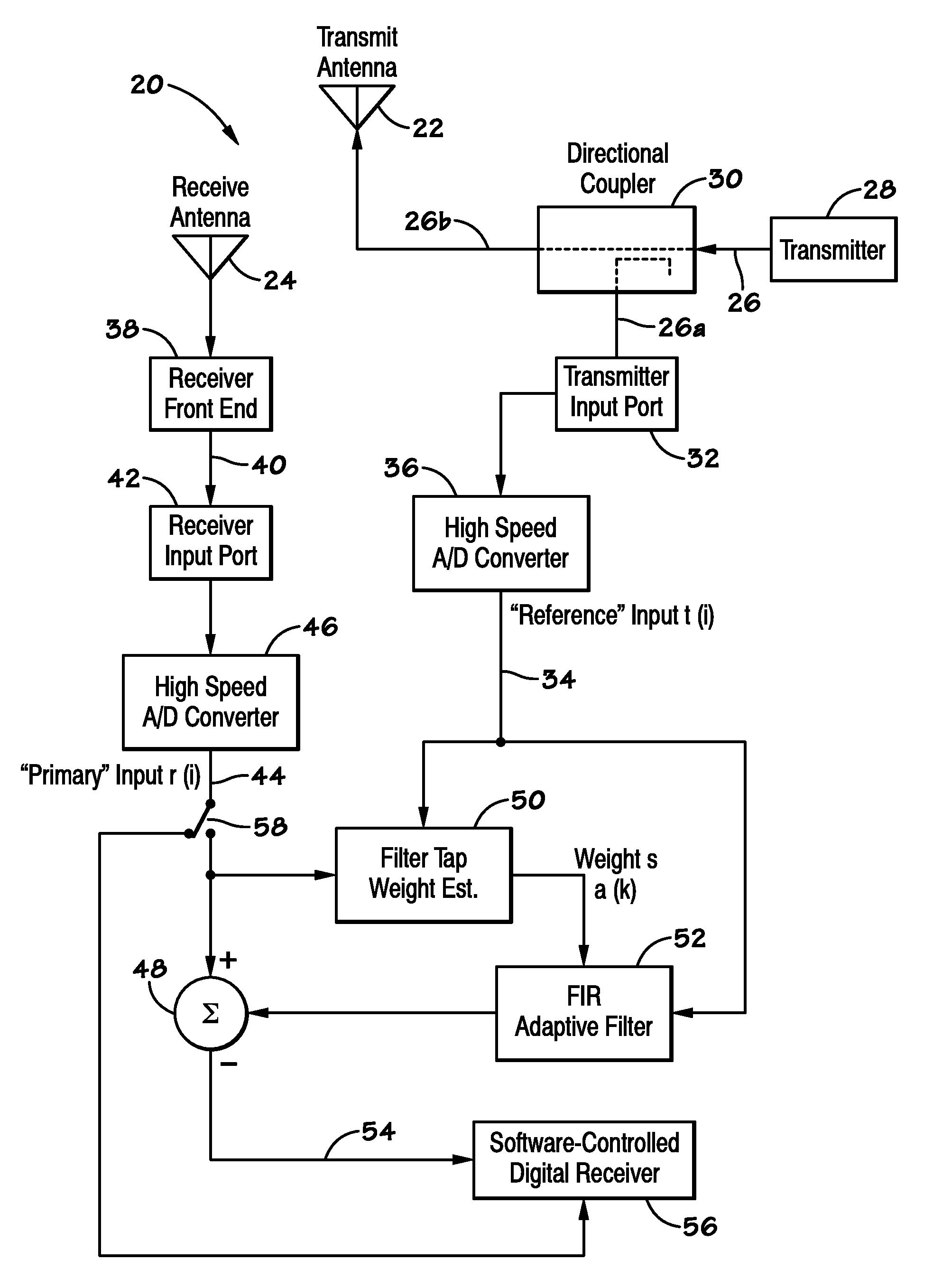
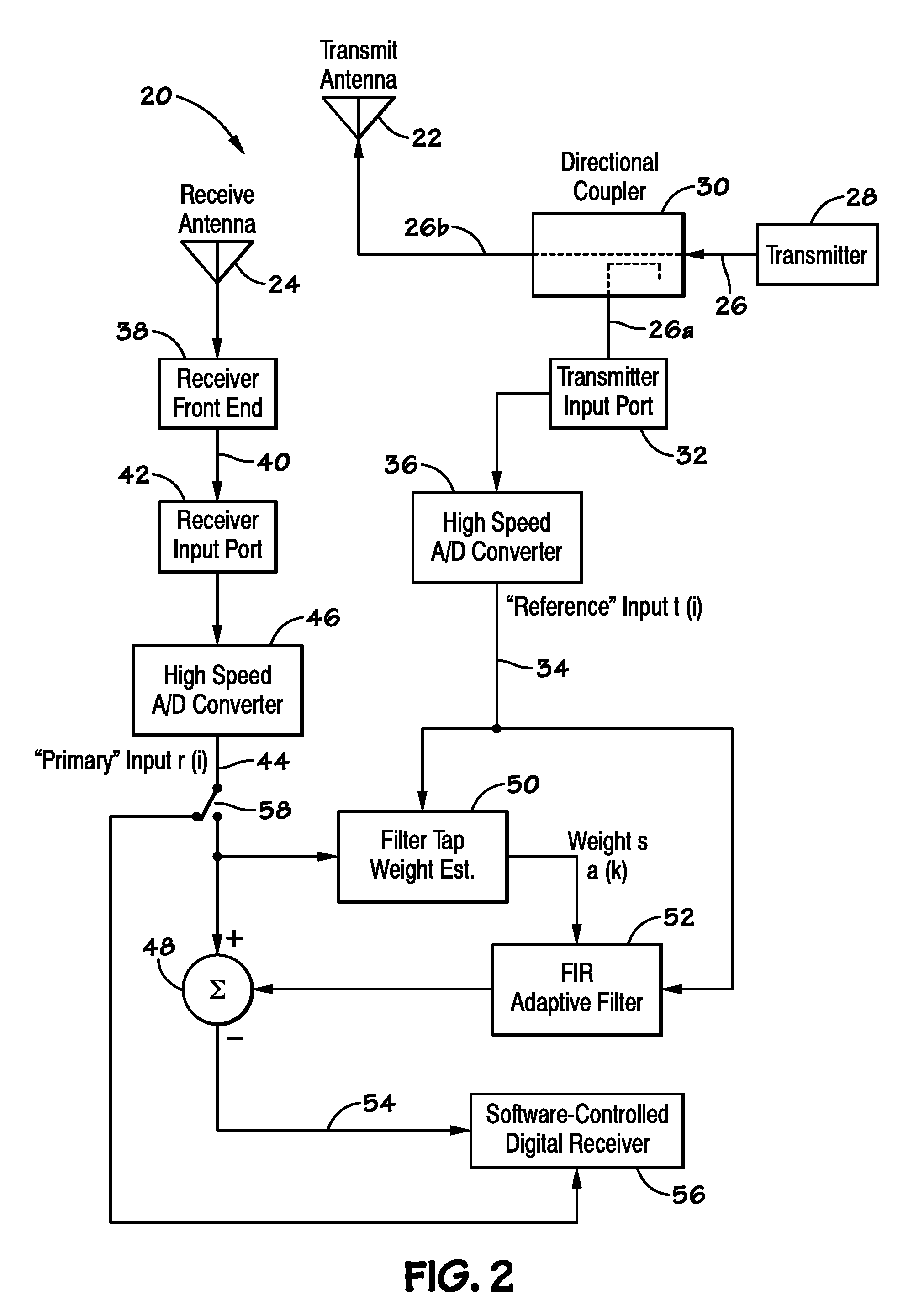
[0005]In one embodiment, a method of managing a communication in a communication network is provided. The method includes operating a network node in the network using a conventional duplexing technique and monitoring transmissions from the network node to determine an expected performance for a division free duplexing (DFD) mode of operation. If the expected performance for DFD operation reaches a threshold performance level, the network node may cease to operate in the conventional duplexing mode and begin operating using a DFD technique.
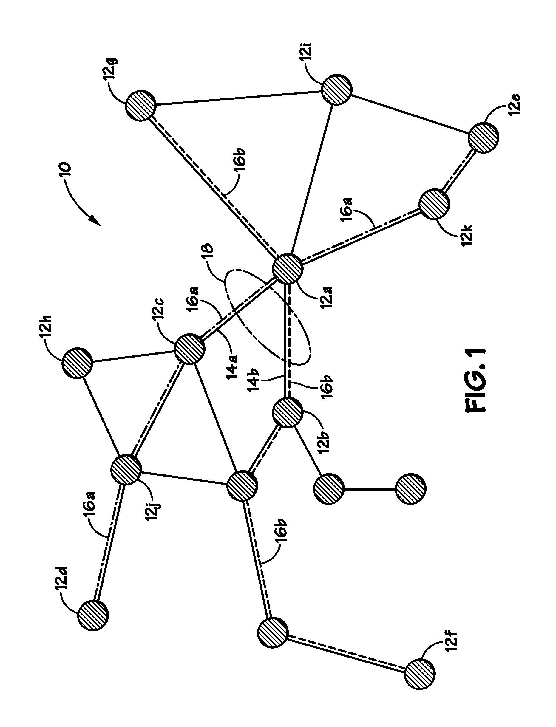
[0006]Another embodiment provides a communication system including a plurality of nodes. One or more nodes of the plurality of nodes, referred to as division free duplex (DFD) enabled nodes, include DFD equipment and are configured to operate in either a DFD mode or a conventional mode. The system also includes a processor configured to substantially control a mode of operation of the DFD enabled nodes.

Problems solved by technology

As the communication route involves the transmission of two different signals, direct interference may occur between the oppositely propagating signals.
Although division duplex systems may enable the near-simultaneous transmitting and receiving of signals, such systems may be insufficient for some communication networks, which have become increasingly complex.
For example, networks using time-division duplex systems may lose time in receiving the signals due to the time-multiplexing of signals, and networks using frequency-division duplex systems may have a limited amount of frequency spectra available for transmission links which support an increasingly large number of communication devices.

Method used


Image

  • Division free duplexing networks
  • Division free duplexing networks
  • Division free duplexing networks

Examples


Embodiment Construction

[0014]A communication network may be an interconnection of devices capable of communicating (e.g., transmitting and receiving data, speech, etc.) with other devices in the network. A communication between two devices in the network may be made through a communication route of links connecting the two devices. For example, in a communication between a first device and a second device, a communication route may refer to a series of links which connect the first and second devices. A “link” may refer to a connection, a transferred signal, etc., and depending on the configuration of the network, links may be made between any communication devices in the network or between devices and other nodes or controllers in the network.

[0015]During a communication, each of the communicating devices may transmit and receive signals. For example, two communicating cellular phones may transmit and receive voice signals (or modulated voice signals) to enable a conversation. Thus, each communication de...


PUM


Abstract

Provided are methods and systems of using division-free duplexing (DFD) in a communication network. Techniques for applying DFD in a communication network may decrease bottlenecks in the network by allowing one or more network nodes to transmit and on substantially the same frequency and at substantially the same time. In one embodiment, one or more nodes in the network may be DFD enabled, and may be configured to operate in either a conventional mode or a DFD mode. The mode of operation of DFD enabled nodes may depend on the quality of signals transmitted to and / or received at the DFD enabled nodes. Further, the mode of operation may change dynamically, and may be substantially controlled by any suitable processor in the network.

Description

BACKGROUND[0001]The subject matter disclosed herein relates to communication systems, and more particularly, to systems and methods of conducting a communication using division free duplexing.[0002]A wireless communication network may include multiple communication devices capable of communicating wirelessly. Communications may be made between the multiple communication devices through various communication routes. Depending on the configuration of the network, communication routes may be made from one communication device to another via central network nodes which connect the devices, or communication routes may include links between any devices of the network. For example, a communication network may include one or more subnetworks, each with one or more central network nodes which link several devices (e.g., cellular phones) within subnetworks of the communication network. Devices in the network may communicate via links within and between the subnetworks. Networks may also be co...

Claims


Application Information

Patent Timeline
Patent Type & Authority Applications(United States)
IPC IPC(8): H04L5/14
CPCH04L5/14H03H2021/0089H04W74/002
Inventor ROSS, JOHN ANDERSON FERGUSHARTMAN, MICHAEL JAMESHERSHEY, JOHN ERIKZINSER, RICHARD LOUIS
Owner GENERAL ELECTRIC CO
Learn More