High-power laser system having delivery fiber with non-circular cross section for isolation against back reflections

Active Publication Date: 2011-10-13
LOCKHEED MARTIN CORP
View PDF4 Cites 22 Cited by
  • Summary
  • Abstract
  • Description
  • Claims
  • Application Information

AI Technical Summary

Benefits of technology

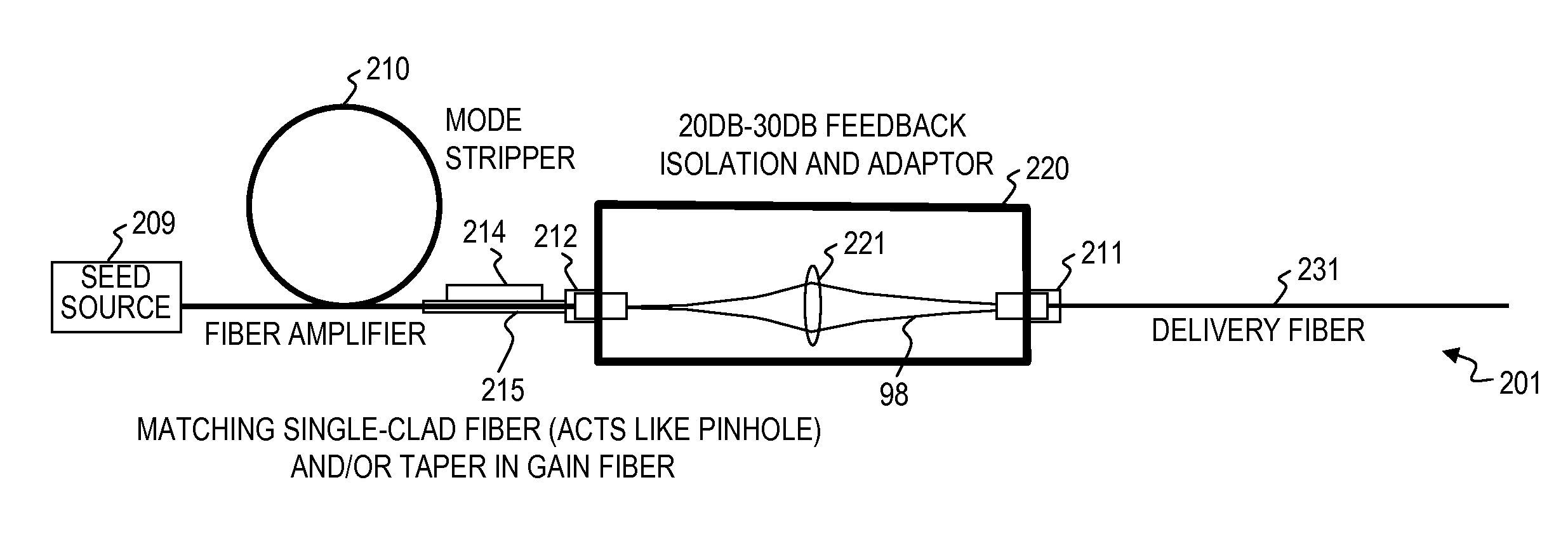
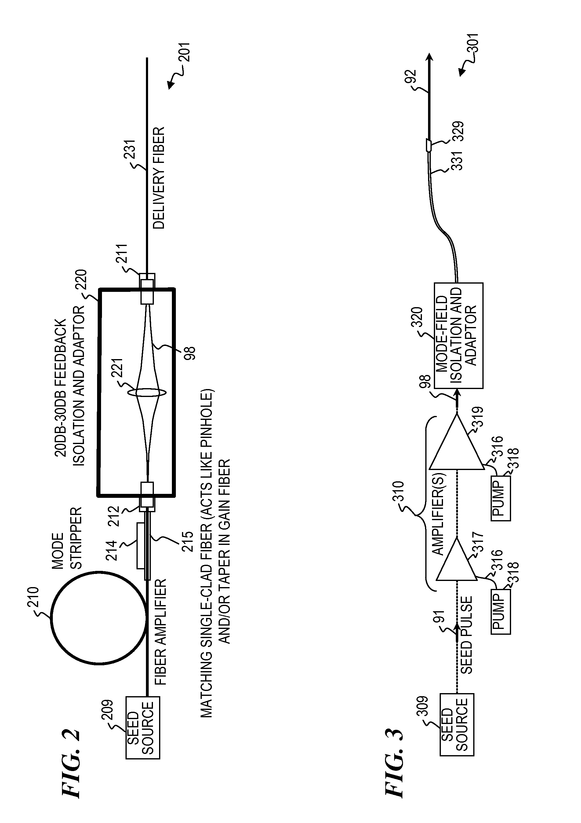
[0026]In some embodiments, the present invention provides a method, an apparatus, and disposable parts thereof for a laser-delivery fiber that has a non-circular core cross-sectional area. In some embodiments, the signal-light output from a relatively small-core gain fiber is directed into a relatively large-core gain fiber that has a non-circular core. In some embodiments, signal light is coupled from a higher brightness fiber to a lower brightness fiber. In some embodiments, the gain fiber can be slightly multimoded. As used herein, the proximal end of the delivery fiber is the light-input end next to the gain fiber of the laser or optical amplifier that provides the signal light, while the distal end is the opposite light-output end at which the signal light is used or directed from. The forward-propagating signal light that enters the proximal delivery fiber is well mixed by the geometry of the core of the delivery fiber, and any reflections from the distal end of the delivery fiber (due, for example, to its design, its use (e.g., from, bones and/or metal pieces in case of a wounded soldier, blood or tissue that may be next to or deposit on the end), or from damage to the distal end of the delivery fiber) that become unwanted backward-propagating light will be further mixed such that multiple modes of the reflected signal light will return from the entry end of the delivery fiber, and only a very small portion (generally at a power level that is 20-30 dB less than the output beam power) will re-enter the gain fiber. In some embodiments, the end of the delivery fiber is angled relative to the output beam of the gain fiber, but has a sufficiently high numerical aperture (e.g., NA=0.2 to 0.3) that substantially all the output beam from the gain fiber enters the core (the signal waveguide) of

Problems solved by technology

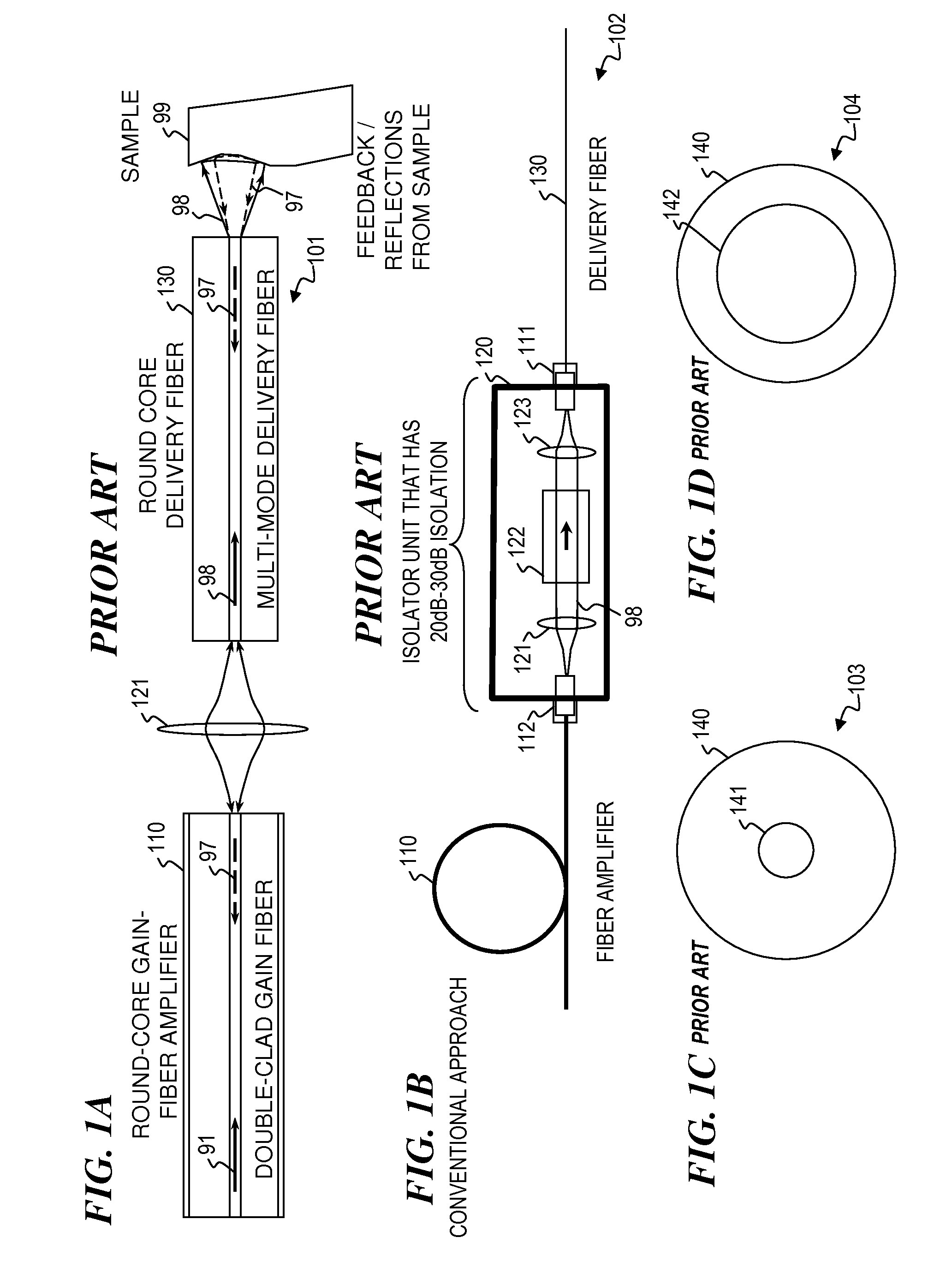
High-power laser systems (for example, laser systems employing a master-oscillator power-amplifier (MPOA) configuration) are subject to damage if a back-reflected signal from a distal end of a delivery fiber re-enters the power-amplifier stage.
Consequently, reflected signals can be coupled into the amplifier and lead to damage of the amplifier or laser.
Such isolators are expensive and complex.

Method used


Image

  • High-power laser system having delivery fiber with non-circular cross section for isolation against back reflections
  • High-power laser system having delivery fiber with non-circular cross section for isolation against back reflections
  • High-power laser system having delivery fiber with non-circular cross section for isolation against back reflections

Examples


Embodiment Construction

[0077]Although the following detailed description contains many specifics for the purpose of illustration, a person of ordinary skill in the art will appreciate that many variations and alterations to the following details are within the scope of the invention. Accordingly, the following preferred embodiments of the invention are set forth without any loss of generality to, and without imposing limitations upon the claimed invention. Further, in the following detailed description of the preferred embodiments, reference is made to the accompanying drawings that form a part hereof, and in which are shown by way of illustration specific embodiments in which the invention may be practiced. It is understood that other embodiments may be utilized and structural changes may be made without departing from the scope of the present invention.

[0078]The leading digit(s) of reference numbers appearing in the Figures generally corresponds to the Figure number in which that component is first intr...


PUM


Abstract

An apparatus and method that provide optical isolation by permitting substantially all forward-propagating light into a delivery fiber from an optical amplifier and substantially preventing backward-traveling light from the delivery fiber entering the optical amplifier without the use of a conventional optical isolator. Eliminating the isolator improves efficiency and reduces cost. Some embodiments use a delivery fiber having a non-circular core in order to spread a single-mode signal into multiple modes such that any backward-propagating reflection is inhibited from reentering the single-mode amplifier. Some embodiments amplify an optical signal in a gain fiber having an output end, output the forward-propagating amplified signal as a high-brightness optical beam (having a first Rayleigh range) into a removable delivery fiber having a non-circular waveguide, output the amplified signal from a distal end of the delivery fiber, and, without the use of a non-linear optical isolator, inhibit backward-propagating light from re-entering the gain fiber.

Description

[0001]This application claims priority benefit under 35 U.S.C. §119(e) to U.S. Provisional Patent Application No. 61 / 343,947 filed on Apr. 12, 2010, titled “HIGH-POWER LASER SYSTEM HAVING DELIVERY FIBER WITH NON-CIRCULAR CROSS SECTION FOR ISOLATION AGAINST BACK REFLECTIONS” by Matthias P. Savage-Leuchs (Attorney Docket 5032.052PV1), U.S. Provisional Patent Application No. 61 / 343,945 filed on Apr. 12, 2010, titled “Apparatus for optical fiber management and cooling” by Yongdan Hu et al. (Attorney Docket 5032.058PV1), U.S. Provisional Patent Application No. 61 / 343,946 filed on Apr. 12, 2010, titled “Beam diagnostics and feedback system and method for spectrally beam-combined lasers” by Tolga Yilmaz et al. (Attorney Docket 5032.062PV1), U.S. Provisional Patent Application No. 61 / 343,948 filed on Apr. 12, 2010, titled “HIGH BEAM QUALITY AND HIGH AVERAGE POWER FROM LARGE-CORE-SIZE OPTICAL-FIBER AMPLIFIERS; SIGNAL AND PUMP MODE-FIELD ADAPTOR FOR DOUBLE-CLAD FIBERS AND ASSOCIATED METHOD” b...

Claims


Application Information

Patent Timeline
IPC IPC(8): H01S3/067
CPCG02B6/02347G02B6/02366G02B6/02371H01S3/1305H01S3/06754H01S3/10015H01S3/0064H01S3/1001G02B6/32H01S3/06783
Inventor SAVAGE-LEUCHS, MATTHIAS P.
Owner LOCKHEED MARTIN CORP
Why Eureka
Try Eureka