
Liquid Ejecting Apparatus and Control Method of Liquid Ejecting Apparatus

a technology of liquid ejecting apparatus and control method, which is applied in the direction of printing, other printing apparatus, etc., can solve the problems of unfavorable image quality, unfavorable image quality, and bleed of recorded images, and achieve the effect of suppressing variations in ejection characteristics

Active Publication Date: 2011-10-13
SEIKO EPSON CORP
View PDF1 Cites 17 Cited by
  • Summary
  • Abstract
  • Description
  • Claims
  • Application Information

AI Technical Summary

Benefits of technology

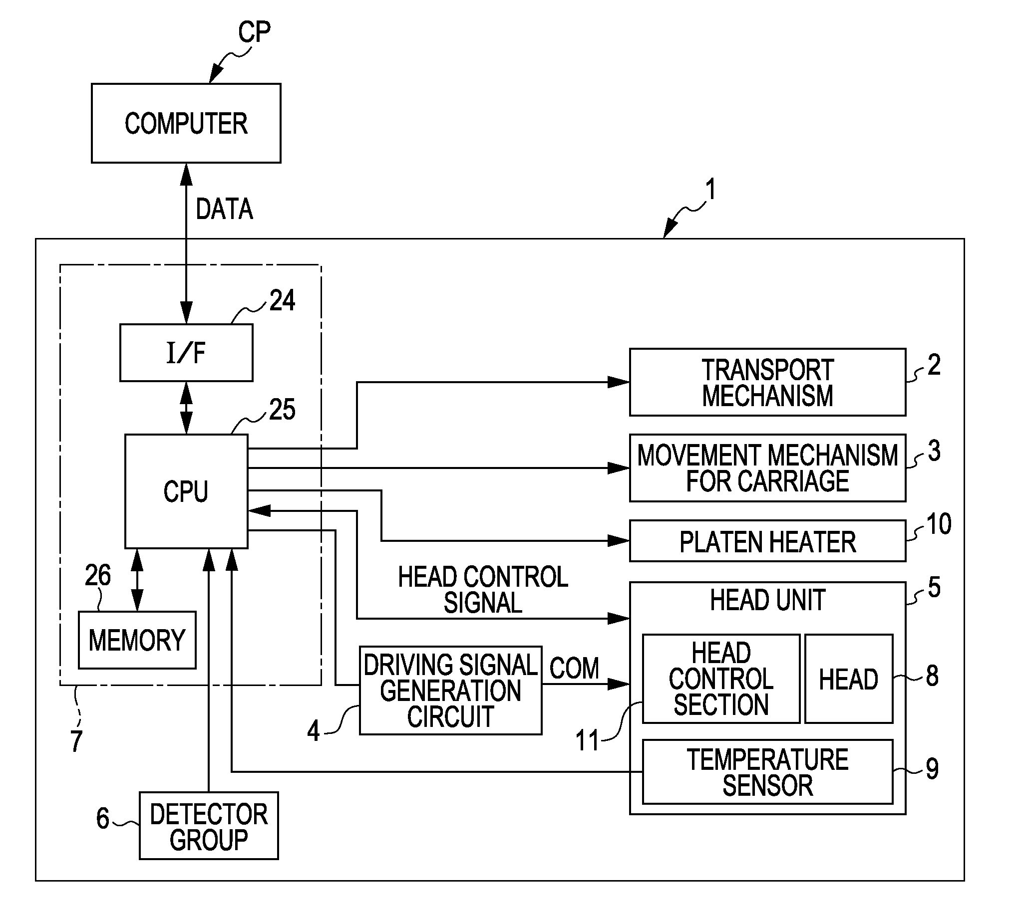
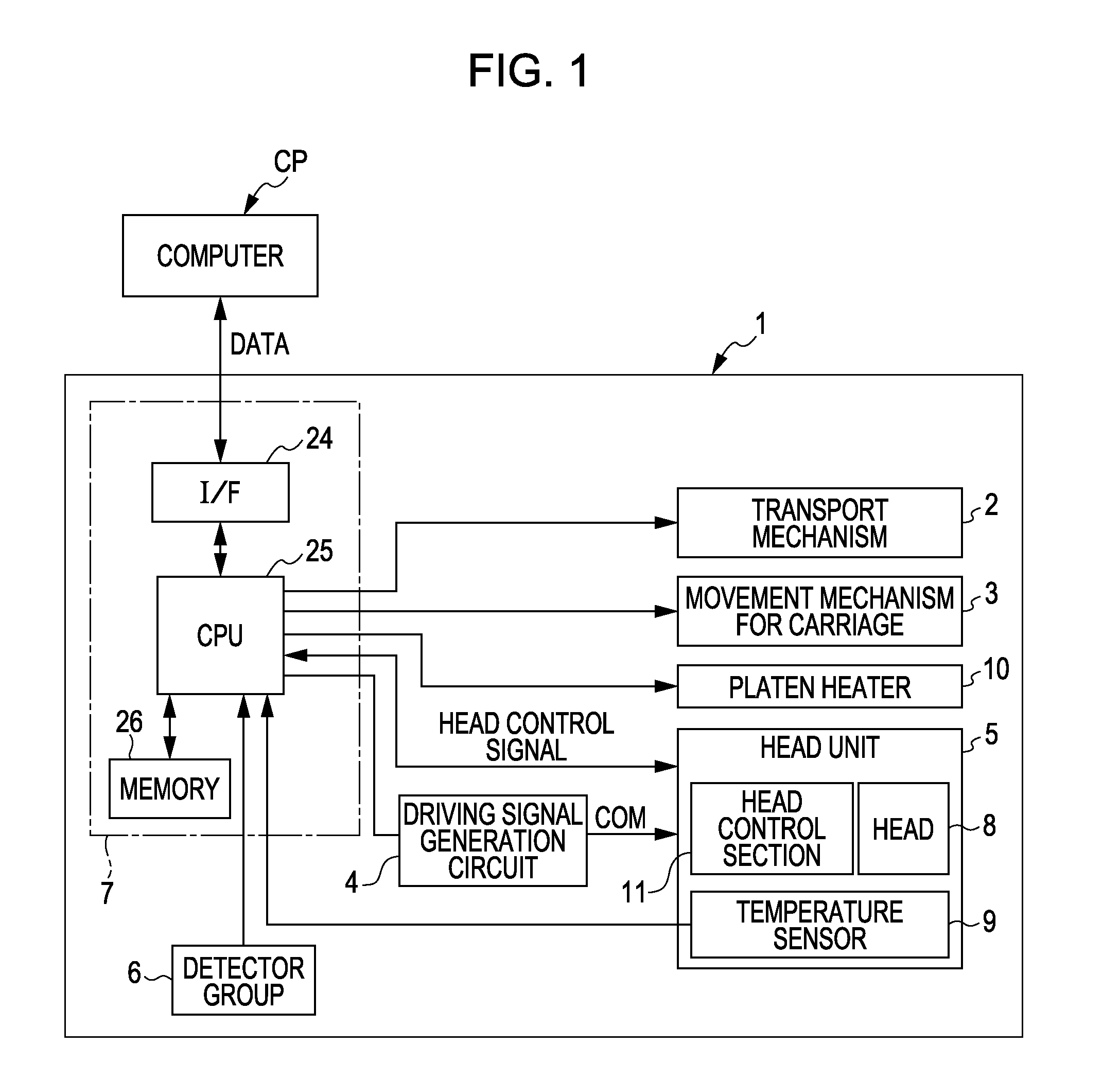
[0009]An advantage of some aspects of the invention is that it provides a liquid ejecting apparatus in which it is possible to suppress variations in the ejection characteristics accompanying a change in temperature, and a control method of a liquid ejecting apparatus.
[0011]According to the above aspect of the invention, when the recording head has moved with respect to the platen to outside of the printing area, the temperature sensor can detect the temperature and the driving waveform is corrected in accordance with the temperature detected by the temperature sensor. Accordingly, it becomes possible to suppress variation in discharge characteristics (discharge amount of a liquid droplet, discharge velocity, formation status of a satellite drop, or the like) accompanying a change in temperature. As a result, variations in the density of an image or the like that is recorded on an impact target is suppressed. In particular, it is possible to prevent variations in the color tone of an image or the like despite a rapid change in temperature after the temperature of the recording head rises after the start of the heating of the platen and the detected temperature changes rapidly, and before a steady state or a state close thereto is attained.
[0014]According to the above configuration, since the temperature is detected at a timing when the recording head relatively moves outside the printing area and then in a low velocity state or has stopped, electrical noise caused by mechanical friction, vibration, or the like, which is generated with relative movement of the recording head, is reduced or disappears in a detection signal, so that superposition of such noise on the detection signal is prevented. As a result, it is possible to more precisely detect the temperature.
[0018]According to the above configuration, since the temperature is detected when the recording head has relatively moved outside the printing area and after an ejection capability restoration process has ended, more precise correction can be performed. That is, by performing an ejection capability restoration process, new liquid is introduced from a liquid supply source into a liquid flow path in the recording head. As a result, the temperature of the liquid is lowered. Therefore, by performing temperature detection after the ejection capability restoration process, it is possible to detect a more precise temperature.
[0020]According to the above configuration, by performing temperature detection and correction of the driving waveform in the printing area, it is also possible to respond to a more significant change in temperature and it becomes possible to more effectively suppress variations in the ejection characteristics accompanying a change in temperature.
[0022]In doing so, since temperature detection is performed every time the recording head relatively moves with respect to the platen so as to move from end to end in a so-called scanning direction for printing, temperature detection or correction of the driving waveform according to it can be promptly performed and printing unevenness is reduced.

Problems solved by technology

Incidentally, since it is hard for the resin film to absorb ink, there is concern that a recorded image may bleed.
Accordingly, there is concern that the density of an image printed on the film may vary undesirably.
As described above, where respective printed parts of an image are joined into one sheet, there is a problem where a difference in density is conspicuous at a boundary portion, thereby resulting in poor image quality.
And when the temperature of the recording head is low at the start of the printing relative to the steady state temperature of the recording head, the resulting temperature change can easily cause the above-mentioned problem.
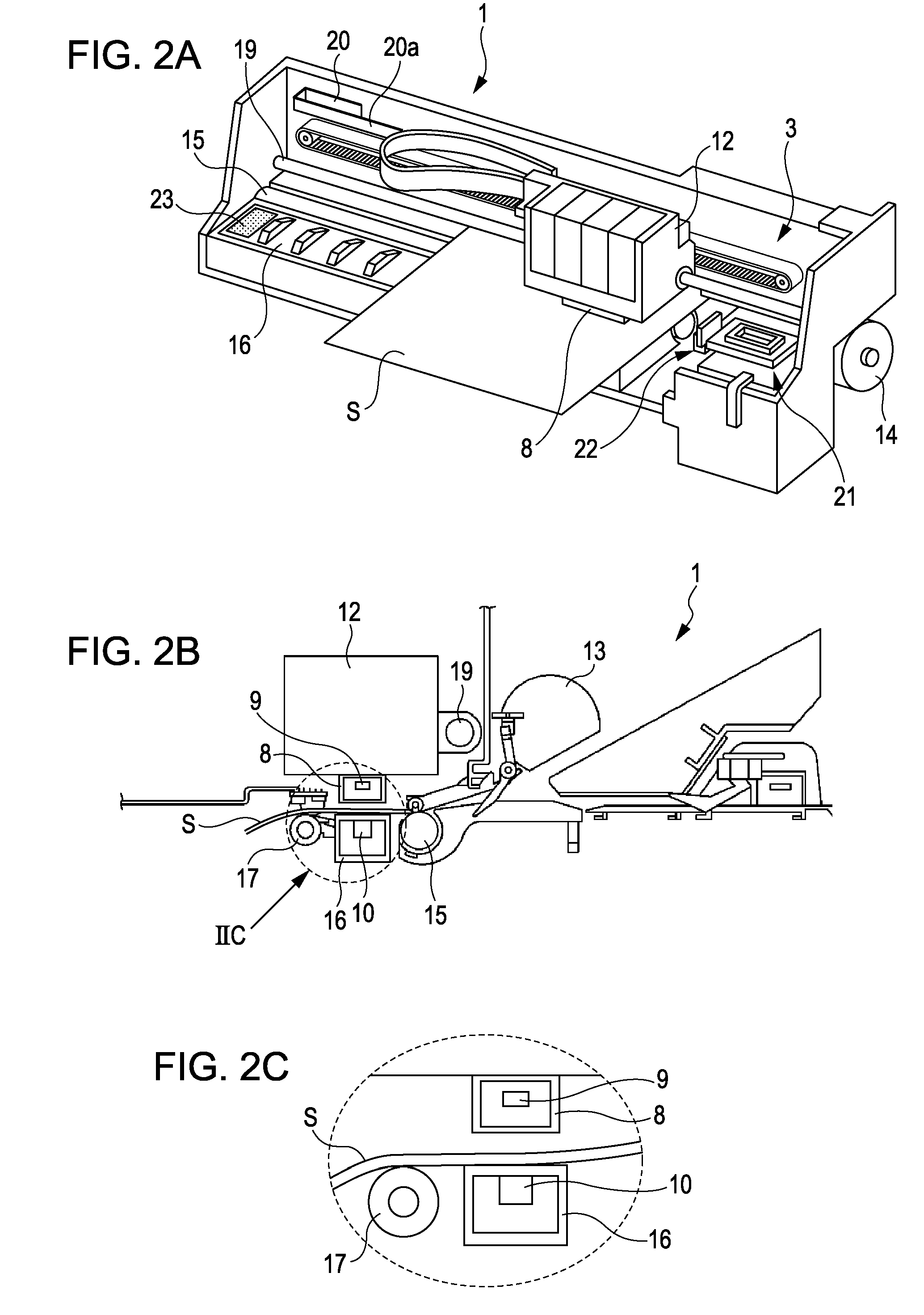
Also, if the recording head is in the printing area, in a case such as during a rise in temperature of the platen, which is heated by the platen heater, since the temperature of the recording head, which faces the platen, is also rising, the detected temperature is not constant and unstable detection may be made.

Method used


Image

  • Liquid Ejecting Apparatus and Control Method of Liquid Ejecting Apparatus
  • Liquid Ejecting Apparatus and Control Method of Liquid Ejecting Apparatus
  • Liquid Ejecting Apparatus and Control Method of Liquid Ejecting Apparatus

Examples


Embodiment Construction

[0034]Hereinafter, the best mode for carrying out the invention will be described with reference to the accompanying drawings. In addition, although in embodiments which are described below, various limitations are given as preferred specific examples of the invention, the scope of the invention is not to be limited to these aspects unless the description of intent to limit the invention is particularly provided in the following explanation. Also, in the following, as a liquid ejecting apparatus according to the invention, an ink jet type recording apparatus (hereinafter referred to as a printer) is taken and described as an example. Although in the following examples, an ink jet printer which ejects ink by using a piezoelectric vibrator is taken and described as an example, a liquid ejecting apparatus which performs boiling by applying heat to liquid and ejects ink by using the force may also be adopted. Also, not only a configuration in which a recording head moves with respect to...


PUM


Abstract

Liquid ejecting apparatus and related methods of operation are disclosed. A liquid ejecting apparatus includes an ejecting head having liquid-ejecting nozzles, a platen disposed to support a recording medium and face the ejecting head, a movement section that moves the ejecting head relative to the platen, a heater that heats the platen, a temperature sensor to detect a temperature of the ejecting head, a driving waveform generation section that generates a driving waveform to drive the ejecting head in accordance with the detected temperature, and a liquid ejection control section that supplies the driving waveform to the ejecting head to eject liquid for printing on the recording medium in a printing area. The driving waveform is generated according to a temperature of the ejecting head that is detected when the ejecting head has come to an area outside the printing area.

Description

[0001]This application claims priority to Japanese Application No. 2010-090873, filed Apr. 9, 2010, the entirety of which is incorporated by reference herein.BACKGROUND[0002]1. Technical Field[0003]The present invention relates generally to a liquid ejecting apparatus such as an ink jet type printer and a control method thereof, and more particularly to a liquid ejecting apparatus having a heater that heats an ejection target, and a control method thereof.[0004]2. Related Art[0005]A typical liquid ejecting apparatus has a liquid ejecting head with nozzles operable to eject various liquids. For example, an image recording apparatus, such as an ink jet type printer (hereinafter simply referred to as a printer) having an ink jet type recording head (hereinafter simply referred to as a recording head, and can also be referred to as a liquid ejecting head, which ejects ink in the form of a liquid) that records an image or the like by ejecting and landing ink in the form of liquid from no...

Claims


Application Information

Patent Timeline
IPC IPC(8): B41J29/38
CPCB41J2/04528B41J2/04563B41J2/0459B41J2/04588B41J2/04581
Inventor OZAWA, KINYAMAKITA, SHUSHITANAKA, RYOICHI
Owner SEIKO EPSON CORP
Learn More