Motor drive device

a technology of motor drive and drive shaft, which is applied in the direction of motor/generator/converter stopper, dynamo-electric gear control, motor/generator/converter stopper, etc., can solve the problems of torque ripple, abnormal noise, and insufficient suppression of so as to suppress torque ripple and abnormal noise, abnormal noise, and abnormal nois

Inactive Publication Date: 2011-10-13
OMRON AUTOMOTIVE ELECTRONICS CO LTD
View PDF6 Cites 13 Cited by
  • Summary
  • Abstract
  • Description
  • Claims
  • Application Information

AI Technical Summary

Benefits of technology

[0025]According to one or more embodiments of the present invention, a motor drive device capable of sufficiently suppressing the occurrence of torque ripple and abnormal noise at the time of motor drive can be provided. In particular, a motor drive device capable of sufficiently suppressing the occurrence of torque ripple and abnormal noise even if the motor rotates at high speed can be provided.

Problems solved by technology

However, the inductive voltage of the motor 550 has a drawback in that torque ripple and abnormal sound occur since a harmonic wave is superimposed on the fundamental wave.
However, in the conventional motor drive device disclosed in Japanese International Patent Publication WO 2005 / 081397 and Japanese Unexamined Patent Publication No. 2006-288076, the occurrence of torque ripple and abnormal noise may not be sufficiently suppressed due to delay in feedback from the rotation calculating portion and the current actual measurement value calculating portion, and delay in calculation of each portion such as the current command value correcting portion if the rotation of the motor is high speed.

Method used


Image

  • Motor drive device
  • Motor drive device
  • Motor drive device

Examples


Embodiment Construction

[0040]Hereinafter, embodiments of the present invention will be described with reference to the drawings. In embodiments of the invention, numerous specific details are set forth in order to provide a more thorough understanding of the invention. However, it will be apparent to one of ordinary skill in the art that the invention may be practiced without these specific details. In other instances, well-known features have not been described in detail to avoid obscuring the invention.

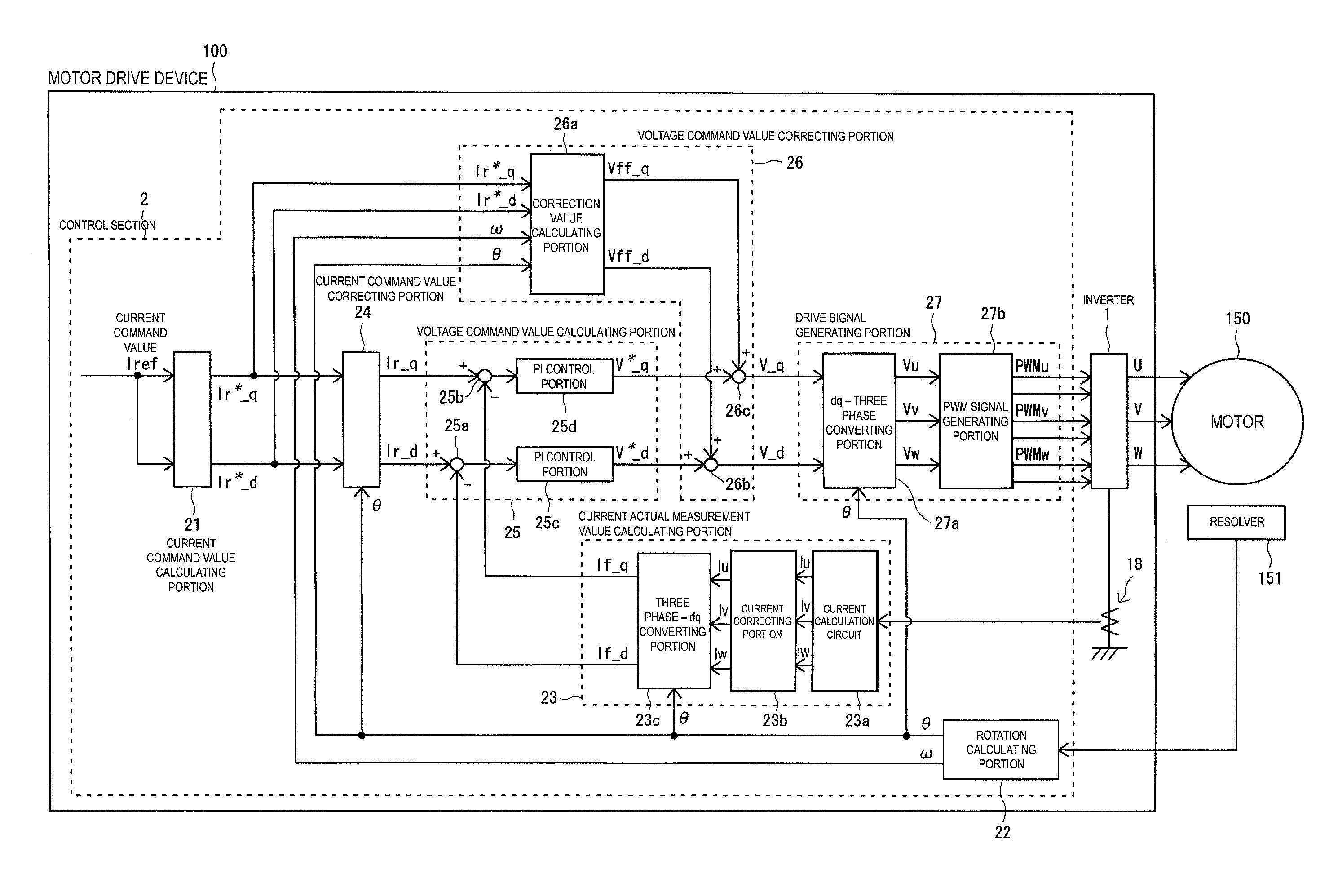
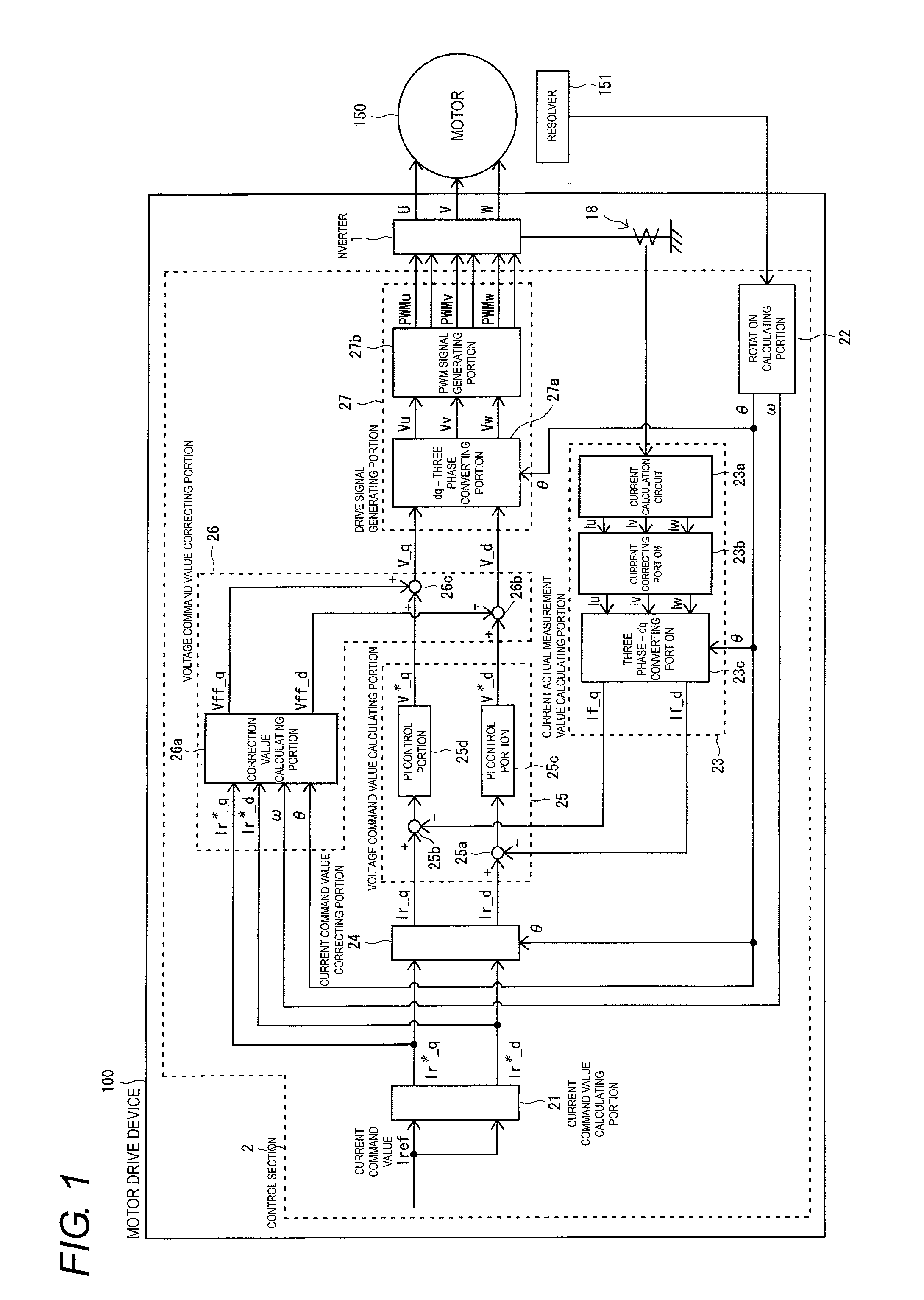
[0041]First, a configuration of a motor drive device 100 according to one embodiment of the present invention will be described with reference to FIG. 1

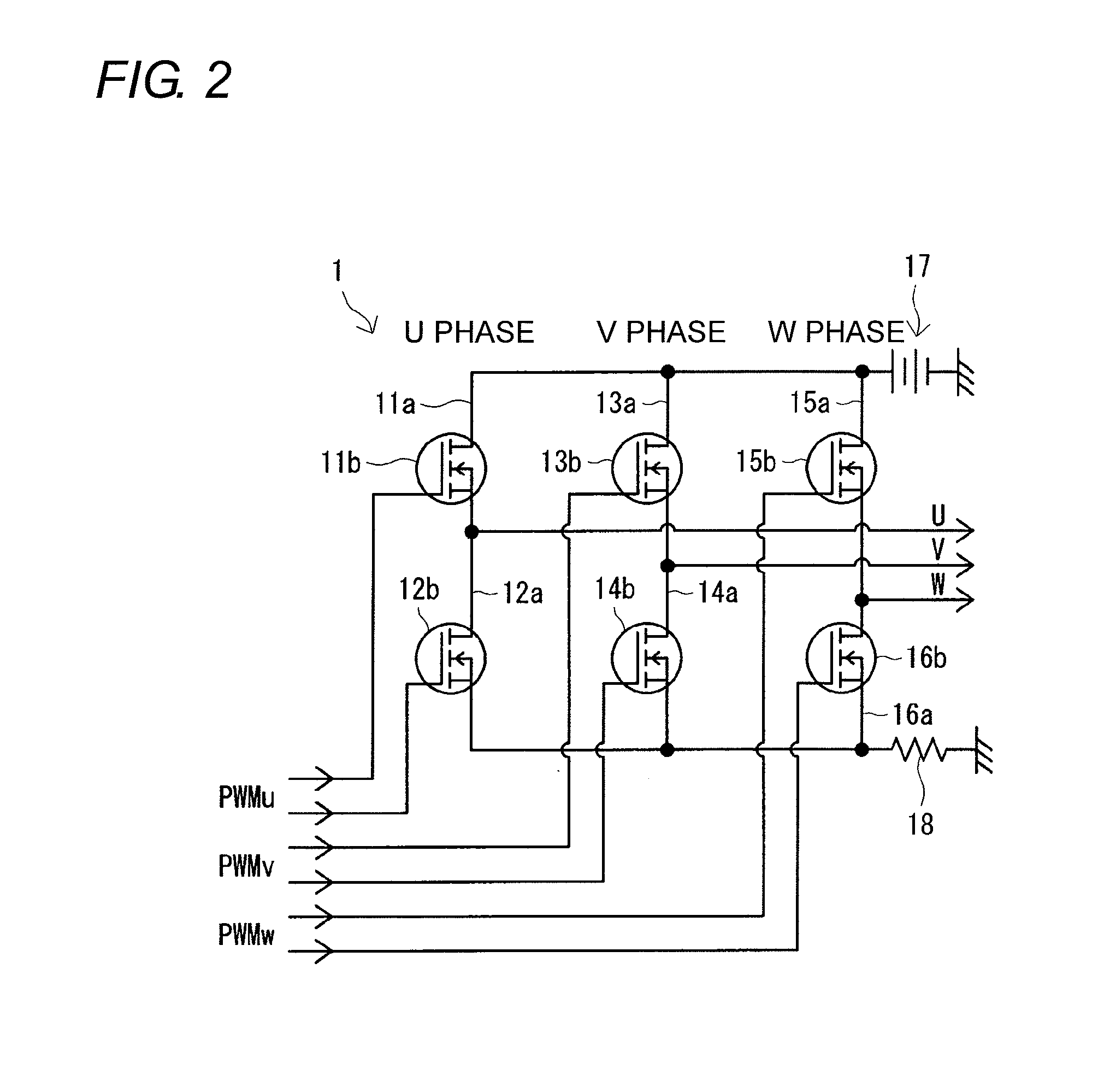
[0042]As shown in FIG. 1, the motor drive device 100 according to one or more embodiments of the present invention includes an inverter 1 for driving a motor 150, and a control section 2 for controlling the inverter 1. The motor 150 is a three phase brushless motor used in an electric power steering device of a vehicle, or the like. The inverter 1 serves a...


PUM


Abstract

A motor drive device has a drive circuit for driving a motor, and a control section for controlling the drive circuit. The control section has a current command value calculating portion for calculating a current command value, a rotation calculating portion for calculating a rotation angle and an angular speed of the motor, a current command value correcting portion for correcting the current command value based on the rotation angle, a voltage command value calculating portion for calculating a voltage command value based on the current command value, a voltage command value correcting portion for correcting the voltage command value based on the current command value and the rotation angle and the angular speed, and a drive signal generating portion for generating a drive signal based on the voltage command value.

Description

BACKGROUND OF THE INVENTION[0001]1. Technical Field[0002]The present invention relates to a motor drive device including a drive circuit for driving a motor, and a control section for controlling the drive circuit.[0003]2. Related Art[0004]A motor drive device 500 including an inverter 510 for driving a motor 550, and a control section 520 for controlling the inverter 510, as shown in FIG. 14, is conventionally known. This motor 550 is, for example, a three-phase brushless motor.[0005]The inverter 510 generates a drive current of three phases based on a PWM signal inputted from the control section 520. The inverter 510 drives the motor 550 by outputting the drive current of three phases to the motor 550.[0006]The control section 520 includes a current command value calculating portion 521, a rotation calculating portion 522, a current actual measurement value calculating portion 523, a voltage command value calculating portion 524, and a drive signal generating portion 525.[0007]A c...

Claims


Application Information

Patent Timeline
Patent Type & Authority Applications(United States)
IPC IPC(8): H02P21/14H02P23/14H02P21/00H02P21/05H02P21/22H02P23/04H02P23/07H02P27/04
CPCH02P21/06
Inventor YABUGUCHI, MICHISADANAKAMURA, TAKENOBUKURATANI, SHINICHI
Owner OMRON AUTOMOTIVE ELECTRONICS CO LTD
Why Eureka
Try Eureka