Conveying screw apparatus for transporting loose material

a technology of conveying screw and loose material, which is applied in the directions of conveying, packaging, transportation and packaging, etc., can solve the problem of reducing the sealing action of the material present between the coil and the inner wall of the tubular body, and achieves the effect of convenient and cost-effectiv

Inactive Publication Date: 2011-10-13
WAM IND
View PDF14 Cites 7 Cited by
  • Summary
  • Abstract
  • Description
  • Claims
  • Application Information

AI Technical Summary

Benefits of technology

[0015]It is therefore one of the main objects of the present invention to provide a conveying screw apparatus for transporting loose material which is free from the above-described drawbacks while being easy and cost-effective to be implemented.

Problems solved by technology

Indeed, in the systems currently in use, in order to prevent a portion of the conveying air from reversing the flow and flowing back from the charging mouth of the hopper thus carrying a portion of the loose material outwards, in a manner highly undesirable for users, it has been suggested to exploit the compression of the loose material itself to prevent the releasing of air and powder towards the mouth of the hopper.
One of the functional limits of this type of system, however, resides in that for the results to be satisfactory, the powders to be transported must be fine and packable, so that plugs may be formed by reducing the pitch of the Archimedes screw, which plugs follow one another to block the air back flow towards the mouth of the hopper.
Furthermore, transporting abrasive loose products by this system is a further problem because the higher friction with the coils of the Archimedes screw puts at risk the coupling tolerances between the screw itself and the tubular body, and therefore reduces the sealing action exerted by the material present between the coils and the inner wall of the tubular body itself.
Firstly, such a jet breaks up the plug and then impresses the energy needed to feed the powder belonging to the plug towards the end user.

Method used


Image

  • Conveying screw apparatus for transporting loose material
  • Conveying screw apparatus for transporting loose material
  • Conveying screw apparatus for transporting loose material

Examples


Embodiment Construction

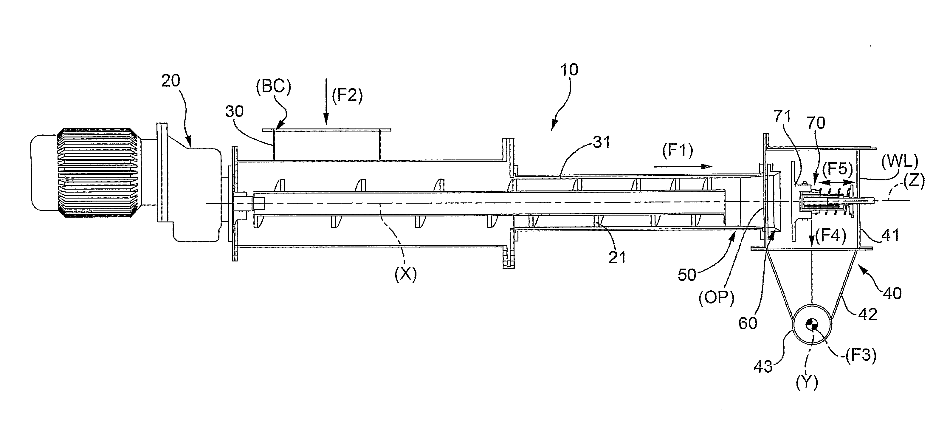
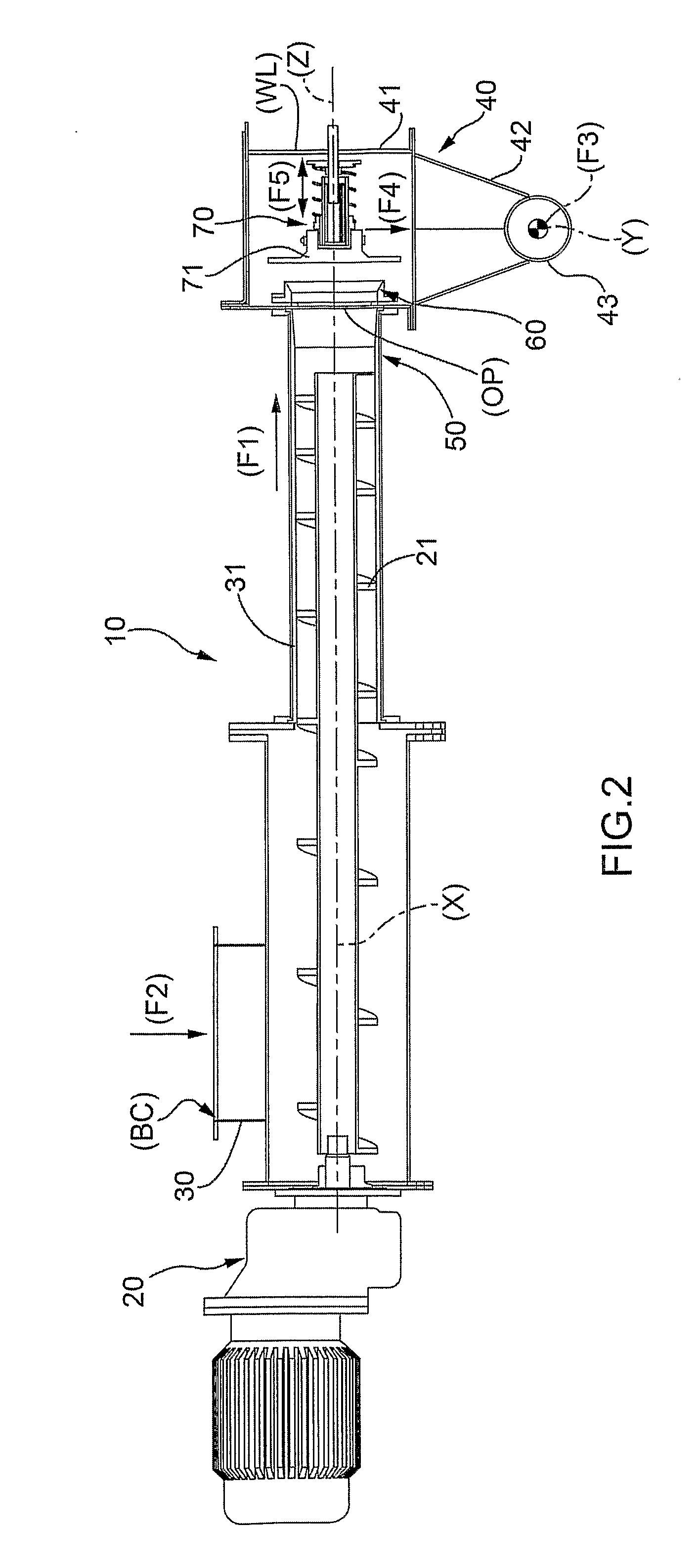
[0025]In FIGS. 1 and 2, numeral 10 indicates as a whole a conveying screw apparatus for transporting loose material object of the present invention.

[0026]Such an apparatus 10 comprises the following devices arranged in series:[0027]a motoreducer unit 20 apt to rotate an Archimedes screw 21 which feeds the loose material according to a first direction defined by a first arrow (F1) substantially parallel to a rotation axis (X) of the Archimedes screw 21 itself;[0028]a charging hopper 30 of the loose material (provided with a charging mouth (BC)), in accordance with a second direction defined by a second arrow (F2) substantially perpendicular to the first direction defined by the first arrow (F1), in a tubular body 31 containing the Archimedes screw 21 and the loose material itself for at least one section of its feed path;[0029]a feeding channel 40 of the loose material towards a user (not shown); the feeding channel 40 is arranged in series to said tubular body 31; and[0030]pneumatic...


PUM


Abstract

A conveying screw apparatus for transporting loose material. The apparatus includes: —a power unit apt to rotate an Archimedes screw pushing the loose material; —a charging hopper of the loose material in a tubular body containing the Archimedes screw and the loose material; —a feeding channel of the loose material towards a user; —pushing elements of the loose material present in the feeding channel; and —a back flow preventing device, preventing the back flow of pushing air together with loose material; such a device closing, in case, a through hole to the feeding channel. The back flow preventing device includes a shutter, provided with a plate, undergoing the action of a helical spring which, in any opening / closing step of the through hole, is always substantially perpendicular to the feeding first direction of the material in the tubular body.

Description

TECHNICAL FIELD[0001]The present invention relates to a conveying screw apparatus for transporting loose material. These conveying screw apparatuses are also known as “powder pumps” in the field.[0002]In particular, the present invention is advantageously, but not exclusively, applied in the transportation of loose materials, such as cement, lime, etc., to which explicit reference will be made in the following description without therefore loosing in generality.BACKGROUND ART[0003]The conveying screws for transporting loose material currently present on the market comprise:[0004]a power unit apt to rotate an Archimedes screw pushing the loose material;[0005]a charging hopper of the loose material in a tubular body containing the Archimedes screw and the loose material for at least a section of its feed path;[0006]a feeding channel of the loose material towards a user; the feeding channel is connected in series to said tubular body;[0007]pneumatic pushing elements of the loose materi...

Claims


Application Information

Patent Timeline
IPC IPC(8): B65G33/14B65G33/24
CPCB65G33/22B65G33/24B65G53/48
Inventor MARCHESINI, VAINERGOLINELLI, LUCA
Owner WAM IND
Why Eureka
Try Eureka