
Method for performing a leak test on a test object

a technology for test objects and leaks, applied in the direction of measurement devices, instruments, structural/machine measurement, etc., can solve the problem of not being able to guide the helium cloud in a controlled manner, and achieve the effect of reducing the consumption of tracer gas, accelerating the leak testing process, and being easy to s

Active Publication Date: 2011-10-13
INFICON HLDG AG
View PDF3 Cites 15 Cited by
  • Summary
  • Abstract
  • Description
  • Claims
  • Application Information

AI Technical Summary

Benefits of technology

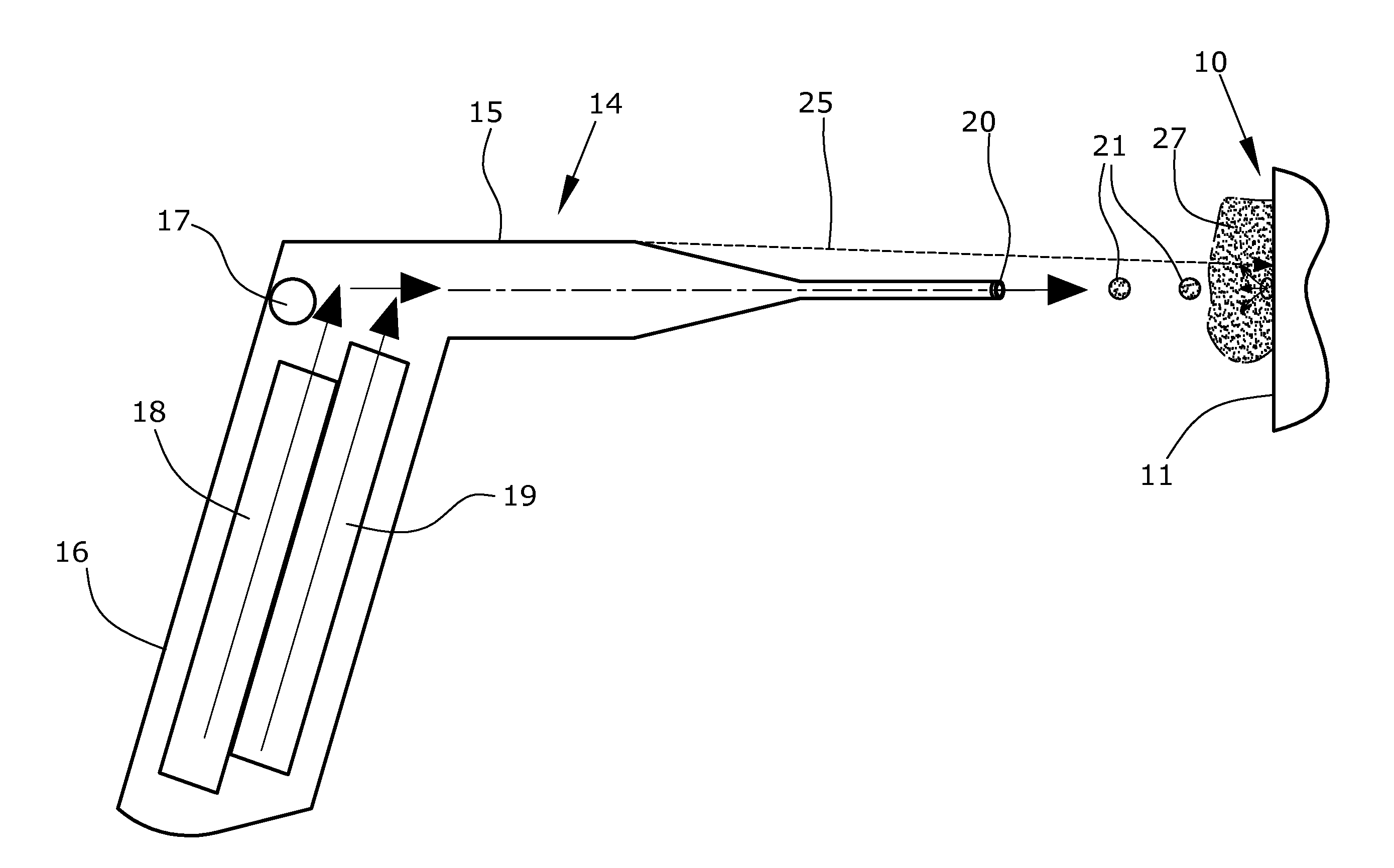
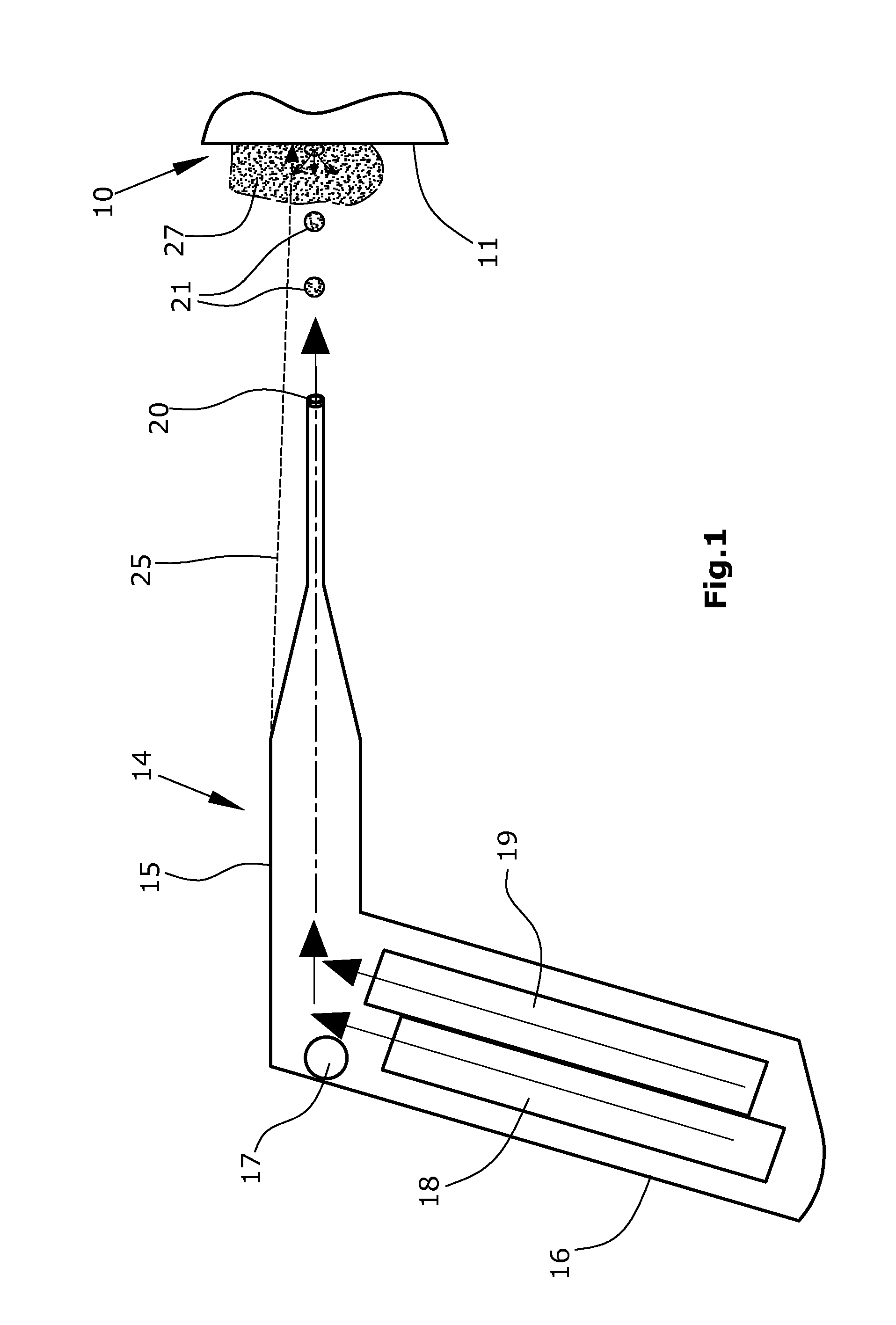
[0004]The method according to the invention is defined by claim 1. In the method of the invention, it is provided that the tracer gas is transported to the test object while contained within soap bubbles. Such soap bubbles will be easily visible to the operator, allowing him or her to see where exactly the tracer gas, preferably helium, is located. This makes it possible to control the flow of soap bubbles and to move it toward the test object by blowing an air-stream onto it, e.g. with the aid of a blower. When contacting the test object, the soap bubbles will burst so that the tracer gas will be released and enter the atmosphere. In this manner, it is made sure that the tracer gas will be brought into the closest vicinity of the wall of the test object and be released there in high concentration. As a result, the consumption of tracer gas is reduced and the leak testing process is accelerated.

Problems solved by technology

Therefore, it is not easy to guide the helium cloud in a controlled manner to the suspected leak sites on the test object so that the helium may enter the test object.

Method used


Image

  • Method for performing a leak test on a test object
  • Method for performing a leak test on a test object

Examples


Embodiment Construction

[0010]According to FIG. 1, a tracer gas, preferably helium, is to be supplied in concentrated form to the outer wall 11 of a hollow test object 10. The test object 10 will be evacuated. In case that a leak exists in said outer wall 11, tracer gas will pass through this leak and thus ingress into the interior of the test object.

[0011]For advancing the tracer gas toward the test object, a blower device 14 is provided which is of a gun-like configuration and comprises a barrel 15 and a grip 16 projecting therefrom at an angle. Blower device 14 includes a blowing source 17 which can be a pressurized-air cartridge or a blower, as well as a liquid tank 18 for liquid polymer and a gas tank 19 for the tracer gas. The soap-like, liquid polymer and the tracer gas will be merged within a bubble-generating means 20 to form soap bubbles 21. Said blowing source 17 is operative to drive the soap bubbles 21 out of the blower device.

[0012]Blower device 14 is further provided with a light source for ...


PUM


Abstract

For leak testing, a tracer gas is advanced to the outer wall (11) of the hollow test object (10) while the test object (10) is in an evacuated state. The tracer gas is discharged from a blower device (14) in the form of soap bubbles (21). When contacting the outer wall (11), the soap bubbles will burst, thus forming a cloud (27) of tracer gas immediately on the outer wall (11). By the invention, it is made easier to localize the invisible tracer gas in the ambient air. Further, the tracer gas can be used more effectively so that the costs for performing the testing process are reduced.

Description

FIELD OF THE INVENTION[0001]The present invention relates to a method for performing a leak test on a test object, said test being of the type wherein a cloud of a tracer gas is generated on an outer wall of the test object and the gas volume in the interior of the test object is tested for the presence of the tracer gas.DESCRIPTION OF THE PRIOR ART[0002]In the leak testing of containers, tubes and technical plants, it is known to generate, externally of the test object, an atmosphere containing tracer gas in concentrated form. Internally of the test object, a vacuum is generated so that, in case that the test object has a leak, tracer gas will be sucked into the interior of the test object. Normally, helium is used as a tracer gas, which is present in small quantities in the atmosphere and is harmless as a breathing gas. The helium will be sprayed into the ambience of the test object, thus forming an invisible helium cloud which is hovering in the air and drifting along with the fl...

Claims


Application Information

Patent Timeline
IPC IPC(8): G01M3/20
CPCG01M3/205G01M3/12
Inventor SCHWARTZ, VLADIMIRCHERNOBROD, BORIS
Owner INFICON HLDG AG
Learn More