
Diagnostic card with micro-fluidic channels and method of construction thereof

a technology of diagnostic cards and fluid channels, which is applied in the direction of laboratory glassware, other domestic objects, chemistry apparatus and processes, etc., can solve the problems of limited shelf life, contamination of the exposed sides of the walls that bound the fluid flow channels within the diagnostic cards by off-gas, and the manufacture of performance of the end produ

Inactive Publication Date: 2011-10-06
WRIGHT INTPROP
View PDF1 Cites 57 Cited by
  • Summary
  • Abstract
  • Description
  • Claims
  • Application Information

AI Technical Summary

Benefits of technology

The invention is about a special card used for medical diagnostics. The card has a layer with channels on both sides, and a layer of clear material on each side. The layers are sealed off from the channels and are bonded together using a laser beam. This design helps to prevent leakage of the channels and ensures the card is durable and reliable. The technical effect of this invention is to provide a more reliable and accurate tool for medical diagnosis.

Problems solved by technology

PSA's are common in the manufacture of micro fluidic cards, however, they present several problems to the manufacture of and performance of the end product.
PSA's degrade over time and thus, they have a limited shelf life.
Thus, the exposed sides of the walls that bound fluid flow channels within the cards become contaminated by the off-gas.
Accordingly, in the case of a micro-fluidic diagnostic device, where biologic and chemical fluids are present, the presence of this foreign off-gas substance may impede or inhibit fluid transfer through the card.
Unfortunately, the variable thicknesses alter the desired dimensions of the micro-fluidic channels, thus, affecting the desired capillary action of the fluidic system.

Method used


Image

  • Diagnostic card with micro-fluidic channels and method of construction thereof
  • Diagnostic card with micro-fluidic channels and method of construction thereof
  • Diagnostic card with micro-fluidic channels and method of construction thereof

Examples


Embodiment Construction

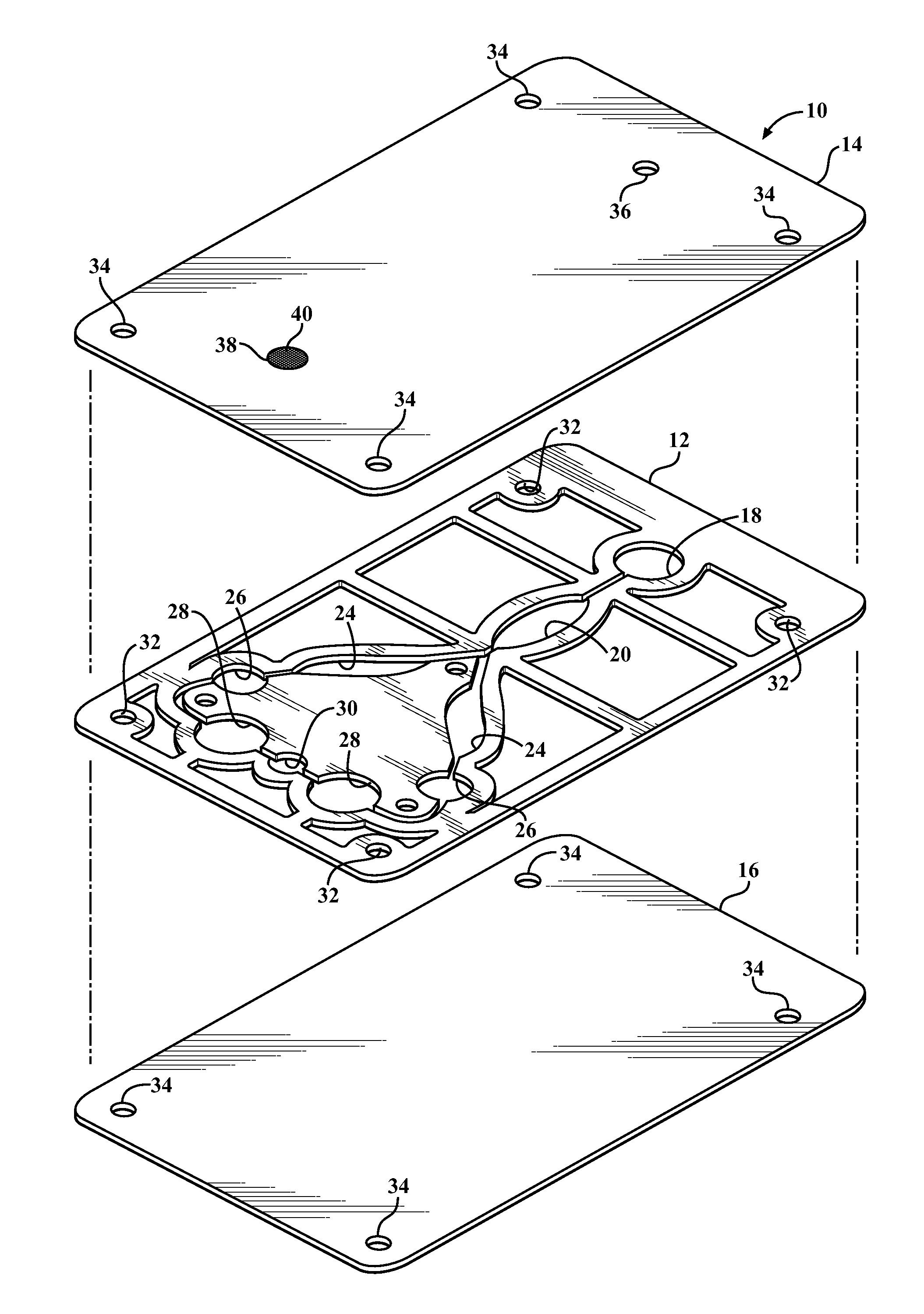
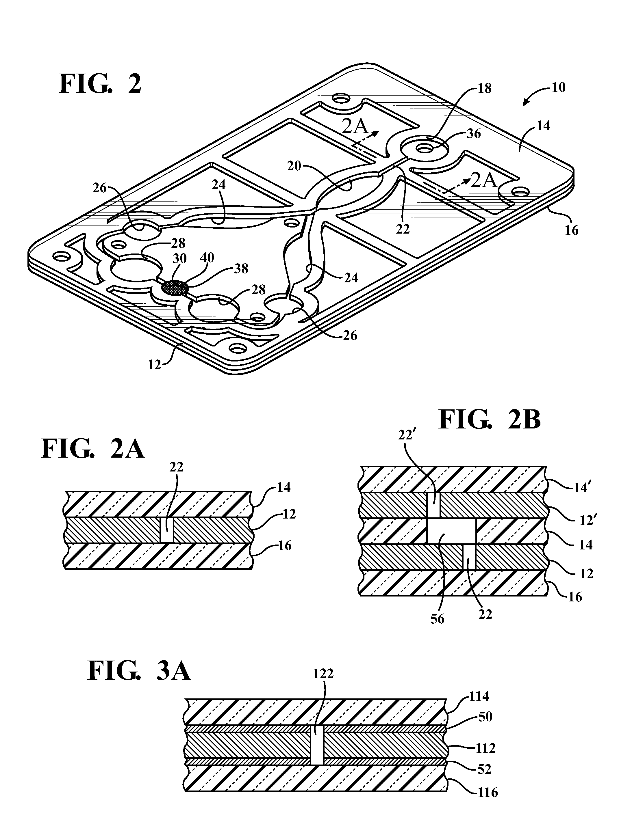
[0017]Referring in more detail to the drawings, FIGS. 1 and 2 illustrate an in vitro diagnostic card 10 constructed in accordance with one presently preferred embodiment of the invention. The process used to construct the card 10 (FIG. 4) makes use of at least one layer of material that is visible in the spectrum of a laser welder 11, shown here, by way of example and without limitation, as an intermediate micro-fluidic channel forming layer 12. The channel forming layer 12 may be constructed by one of many methods, including but not limited to: laser cutting, rule-die cutting, water jet cutting, punch-die forming and injection molding. The channel forming layer 12 is opaque, and thus, absorbs a suitable amount of energy from a laser welding spectrum, also referred to as laser beam 13, to form a bond between the intermediate layer 12 at least one, and shown here as a pair of outer first and second layers, also referred to as top and bottom layers 14, 16. The opaque, intermediate car...


PUM

PropertyMeasurementUnit
translucentaaaaaaaaaa
energyaaaaaaaaaa
shapeaaaaaaaaaa

Abstract

An in vitro diagnostic card and method of construction thereof is provided. The card includes an intermediate layer having opposite faces with at least one channel extending through the faces. A translucent first layer is fixed to one of the faces of the intermediate layer and a translucent second layer is fixed to the other of the faces of the intermediate layer opposite the translucent first layer. The channel in the intermediate layer is substantially sealed off by the first and second layers. Further, an opaque material that is absorbent to laser beam energy bonds the intermediate layer to the first and second layers.

Description

CROSS-REFERENCE TO RELATED APPLICATION[0001]This application claims the benefit of U.S. Provisional Application Ser. No. 61 / 318,984, filed Mar. 30, 2010, which is incorporated herein by reference in its entirety.BACKGROUND OF THE INVENTION[0002]1. Technical Field[0003]This invention relates generally to diagnostic cards having micro-fluidic channels and to their methods of construction.[0004]2. Related Art[0005]Typically, micro fluidic cards, or fluid networks are comprised of a three dimensional shape, molded in plastic and assembled using pressure sensitive adhesives or some other standard intermediate bonding agent. The geometry is created in a computer aided design (CAD) system, or other design tool, at which point an injection molding tool is produced reflecting the geometry. The tool is placed in an injection molding press, and plastic is injected into the cavity, representing the desired shape, thus producing a component of the final assembly. The entire process of designing,...

Claims


Application Information

Patent Timeline
Patent Type & Authority Applications(United States)
IPC IPC(8): B01L3/00B29C65/16
CPCB01L3/502707Y10T156/103B01L2200/10B01L2300/0816B01L2300/0887B29C65/1635B29C65/1667B29C66/1122B29C66/43B29C66/53462B29C66/543B29L2031/756B29C65/4815B29C65/1645B29C65/1664B29C65/168B29C66/836B01L2200/0684B29C66/652B29C66/71B29K2995/0027B29K2023/00B29K2023/06B29K2023/12B29K2055/02
Inventor JACKINSKY, STEVE W.KROEHI, PETER W.WRIGHT, DAVID W.
Owner WRIGHT INTPROP
Learn More