
Image processing method, computer-readable storage medium, image processing apparatus, and imaging apparatus

a technology of image processing and computer-readable storage media, applied in the field of image processing methods, image processing apparatus, image processing apparatus, etc., can solve the problems of significant unnatural, unnatural effect of flare, and inability to execute the method, so as to accurately extract the influence of color flare

Active Publication Date: 2011-10-06
NIKON CORP
View PDF6 Cites 60 Cited by
  • Summary
  • Abstract
  • Description
  • Claims
  • Application Information

AI Technical Summary

Benefits of technology

The present patent application provides an image processing method and apparatus that can extract information about a flare component from a shot image without using information about the bright point image component. This allows for accurate extraction of the flare component from the occurrence area of the flare, and the influence of the flare on the occurrence area can be estimated. The method and apparatus can be used in image processing for color correction and other applications.

Problems solved by technology

This color flare gives an unnatural impression to the shot image, and particularly, it is significantly unnatural compared to an achromatic flare.
However, the flare component actually occurred in the shot image depends not only on the imaging characteristic of the shooting optical system but also on a wavelength spectrum included in the bright point, so that it is difficult for the electronic camera described in Patent Document 1 to estimate the flare component with a sufficient accuracy.
Further, even if it is tried to execute a flare reduction method described in Patent Document 1 using software of a computer, since data sufficient for estimating the flare component is not given to a normal shot image (JPEG image, for example), the execution of the method is not possible.

Method used


Image

  • Image processing method, computer-readable storage medium, image processing apparatus, and imaging apparatus
  • Image processing method, computer-readable storage medium, image processing apparatus, and imaging apparatus
  • Image processing method, computer-readable storage medium, image processing apparatus, and imaging apparatus

Examples


first embodiment

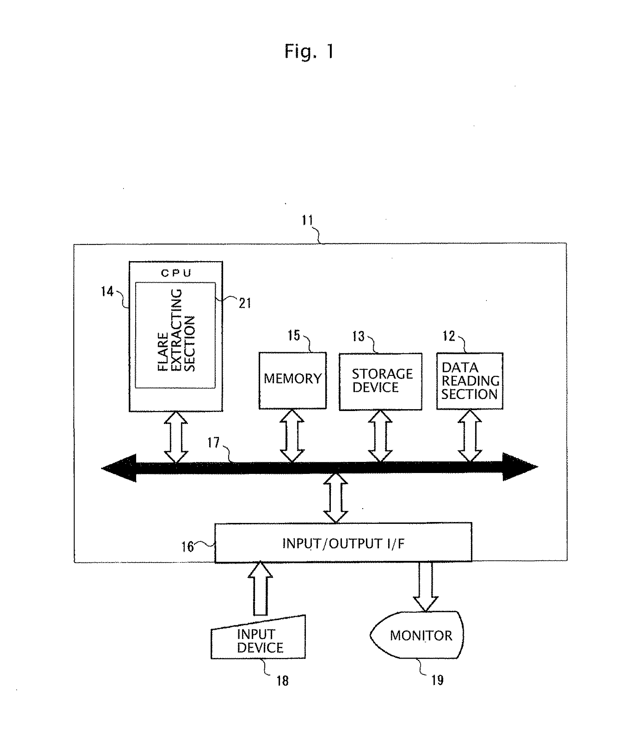
[0062]Hereinafter, a first embodiment of the present application will be described. FIG. 1 is a block diagram illustrating a configuration example of an image processing apparatus of the present embodiment. The image processing apparatus of the present embodiment is formed of a computer 11 in which an image processing program is installed.

[0063]The computer 11 illustrated in FIG. 1 includes a data reading section 12, a storage device 13, a CPU 14, a memory 15, an input / output I / F 16, and a bus 17. The data reading section 12, the storage device 13, the CPU 14, the memory 15, and the input / output I / F 16 are mutually connected via the bus 17. Further, an input device 18 (a keyboard, a pointing device or the like) and a monitor 19 are respectively connected to the computer 11 via the input / output I / F 16. Note that the input / output I / F 16 receives respective inputs from the input device 18, and it also outputs data for display to the monitor 19.

[0064]The data reading section 12 is used ...

second embodiment

[0125]Hereinafter, a second embodiment of the present application will be described.

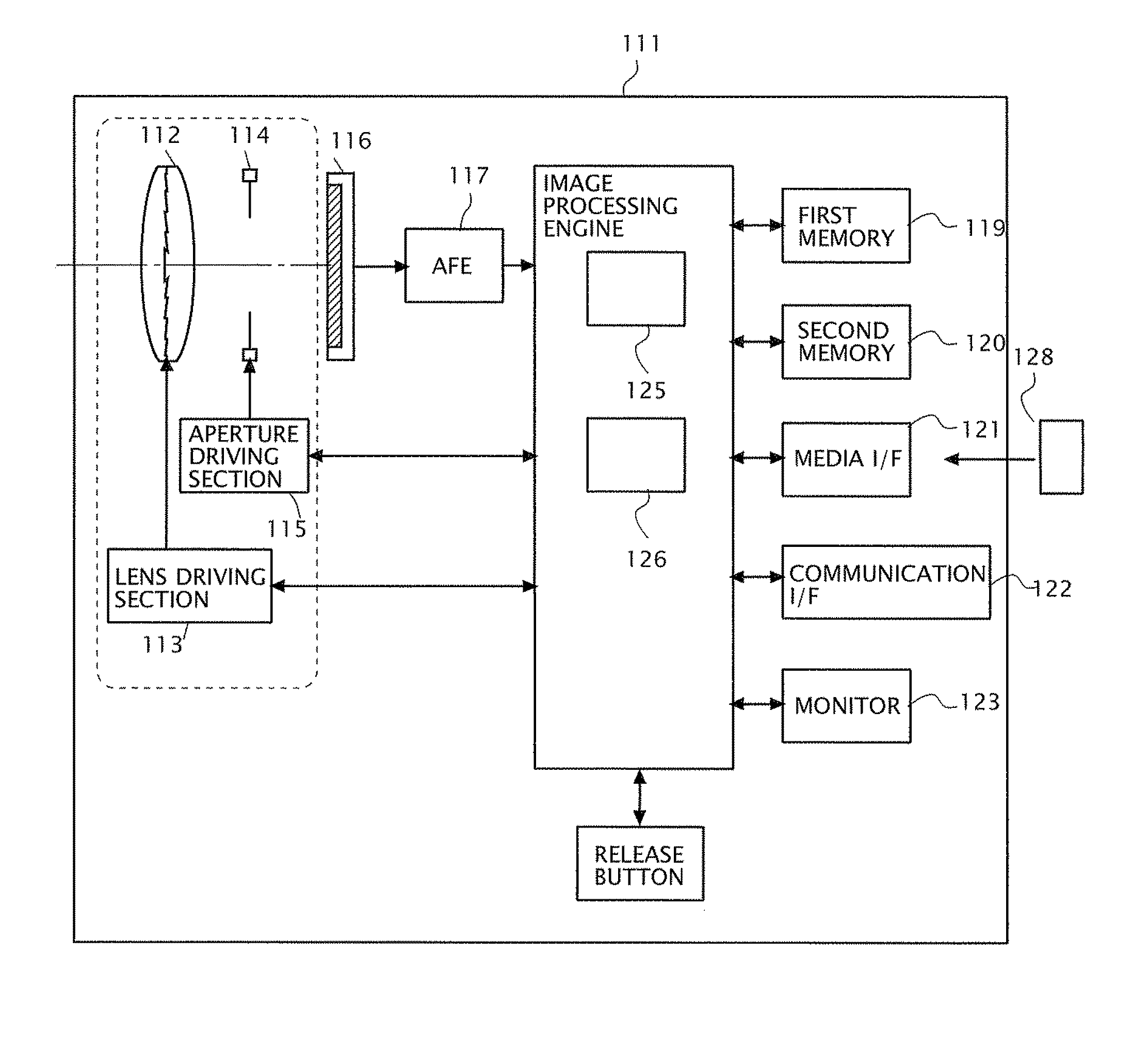
[0126]FIG. 22 is a block diagram illustrating a schematic configuration of an electronic camera. As illustrated in FIG. 22, an electronic camera 111 includes a shooting optical system 112, a lens driving section 113, an aperture 114, an aperture driving section 115, a color imaging device 116, an AFE 117, an image processing engine 118, a first memory 119, a second memory 120, a media I / F 121, a communication I / F 122, a monitor 123 and a release button 124, and among the above, the lens driving section 113, the aperture driving section 115, the AFE 117, the first memory 119, the second memory 120, the media I / F 121, the communication I / F 122, the monitor 123, and the release button 124 are respectively connected to the image processing engine 118. Further, the shooting optical system 112 is a high-functional shooting optical system including a DOE lens, for example.

[0127]The first memory 119 is forme...

third embodiment

Modified Example of Third Embodiment

[0202]Note that although the color corrected component extraction processing section 22 in the third embodiment forms the reference image IR″ in steps S193 to S195, the formation of reference image IR″ can also be omitted. In that case, the color corrected component extraction processing section 22 is only required to execute the following steps S193′ to S195′, instead of steps S193 to S195. Note that also in this case, it is assumed that the correction target color component is the R component.

[0203]Step S193′: The color corrected component extraction processing section 22 refers to the R component inside the flare area Ai and outside the saturation area Si, calculates a maximum value of the R component, and sets the value as a reference value T. This reference value T is used as a reference for calculating the color corrected component.

[0204]Step S194′: The color corrected component extraction processing section 22 subtracts the reference value ...


PUM


Abstract

Information of a flare component is extracted from a shot image without using shooting condition data such as wavelength spectrum data of a bright point and imaging characteristic data of a shooting optical system. To achieve this, an aspect of an image processing method of the present application includes an input step inputting a processing target image obtained by a shooting optical system, an estimating step estimating an ideal bright point image component included in an occurrence area of a flare in the processing target image, an extracting step extracting a real bright point image component including a flare component from the occurrence area, and a calculating step calculating a difference between the ideal bright point image component and the real bright point image component as an index of the flare component included in the occurrence area.

Description

CROSS-REFERENCE TO RELATED APPLICATIONS[0001]This application is based upon and claims the benefit of priority from Japanese Patent Application No. 2010-077996 (filed on Mar. 30, 2010), Japanese Patent Application No. 2010-283183 (filed on Dec. 20, 2010), and Japanese Patent Application No. 2010-283188 (filed on Dec. 20, 2010), the entire contents of which are incorporated herein by reference.BACKGROUND[0002]1. Field[0003]The present application relates to an image processing method, a computer-readable storage medium, an image processing apparatus, and an imaging apparatus extracting information of a flare from a shot image.[0004]2. Description of the Related Art[0005]When shooting is performed by a shooting optical system having a DOE (Diffractive Optical Element), if a quite highly luminous object (bright point) exists in a shooting angle of view, a flare (color flare) with color blurring occurs in a periphery of a bright point image on a shot image. This color flare gives an unn...

Claims


Application Information

Patent Timeline
Patent Type & Authority Applications(United States)
IPC IPC(8): H04N5/225G06K9/00
CPCH04N9/045H04N5/3572H04N25/61H04N23/84H04N25/611
Inventor HIKOSAKA, KENTARO
Owner NIKON CORP
Learn More